AI technical title is built by Patsnap AI team. It summarizes the technical point description of the patent document.
A technology of cloth rewinding machine and cloth roll, applied in the field of cloth processing, can solve the problems of cloth damage, irregular folding and tension fluctuation, etc.
Active Publication Date: 2018-09-14
江苏盐渎百鸣农业有限公司
View PDF10 Cites 2 Cited by
Summary
Abstract
Description
Claims
Application Information
AI Technical Summary
This helps you quickly interpret patents by identifying the three key elements:
Problems solved by technology
Method used
Benefits of technology
Problems solved by technology
The unwinding structures in the above-mentioned patent documents are all fixedly arranged on the frame, and the cloth feeding rollers are arranged on the swinging structure. Therefore, during the swinging process, the cloth stretches and relaxes, causing tension fluctuations, and only the cloth is damaged and folded. the irregular
Method used
Image
Click on the blue label to locate the original text in one second.
Reading with bidirectional positioning of images and text.
Examples
Embodiment 1
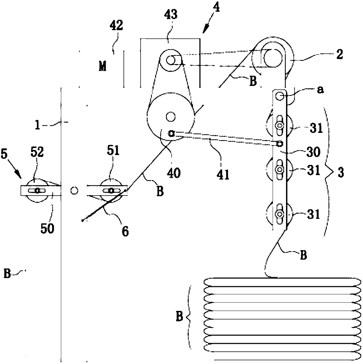
[0022] A swinging cloth machine, such as Figure 4 As shown, it includes a bracket and a swinging cloth winding device arranged on the bracket, the swinging cloth winding device is used for unwinding and folding the cloth roll, and the swinging cloth winding device swings the cloth roll.
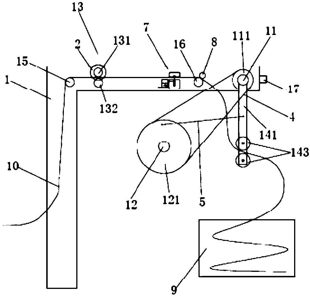
[0023]The swinging cloth collecting device includes a first driving pulley 1, a first driving pulley shaft 2, a first connecting rod 3, a first transmission belt 4, a first driven pulley 5, a cloth winding roller 6, a first driven belt Axle 7, triangle transmission plate 8, second link 9, third link 10, fourth link 11, second driven pulley shaft 12, second driven pulley 13, fifth link 14, second The transmission belt 15, the second driving pulley shaft 16, the second driving pulley 17, the cloth feeding roller 18, the first driving pulley shaft 2 is rotatably arranged on the bracket, and the first driving pulley 1 is fixedly arranged on the first driving pulley. On a driving pulley shaft 2 ...
Embodiment 2
[0029] A swinging cloth machine, such as Figure 5 As shown, it includes a bracket and a swinging cloth winding device arranged on the bracket, the swinging cloth winding device is used for unwinding and folding the cloth roll, and the swinging cloth winding device swings the cloth roll.
[0030] The swinging cloth collecting device includes a first driving pulley 1, a first driving pulley shaft 2, a first connecting rod 3, a first transmission belt 4, a first driven pulley 5, a cloth winding roller 6, a first driven belt Axle 7, triangle transmission plate 8, second link 9, third link 10, fourth link 11, second driven pulley shaft 12, second driven pulley 13, fifth link 14, second The drive belt 15, the second drive pulley shaft 16, the second drive pulley 17, the cloth feed roller 18 and the fourth drive belt 19, the first drive pulley shaft 2 is rotatably arranged on the bracket, and the first drive pulley 1 is fixed It is arranged on the first driving pulley shaft 2, one ...
PUM
Abstract
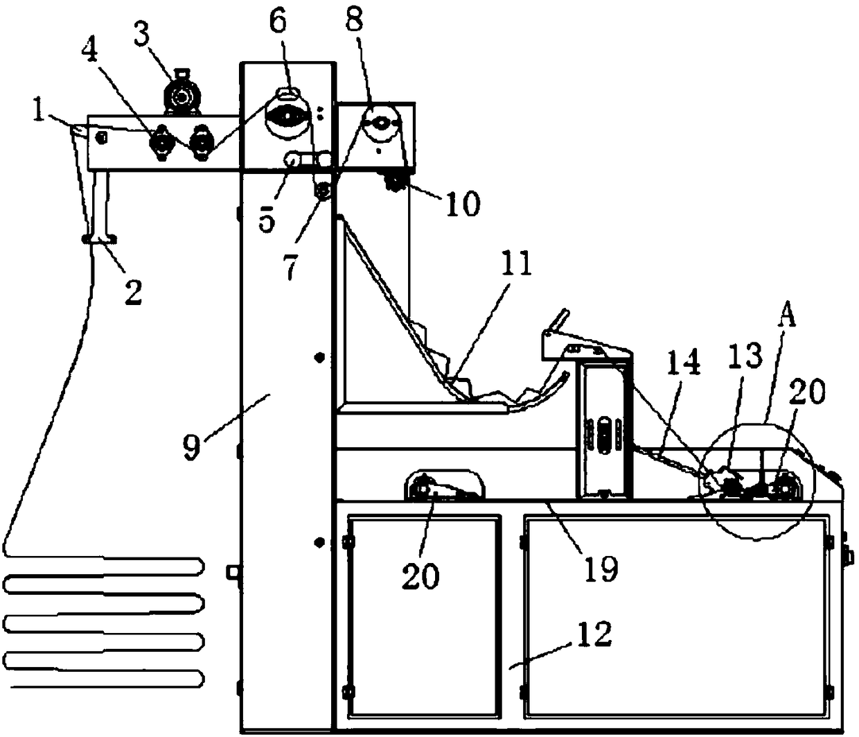
The invention relates to a swinging cloth collecting machine. The swinging cloth collecting machine comprises a support and a swinging cloth collecting device arranged on the support; and the swingingcloth collecting device is used for unwinding and folding a cloth roll. The swinging cloth collecting machine is characterized in that the swinging cloth collecting device swings the cloth roll; dueto the fact that cloth conveying rollers and a cloth roll roller are both arranged on a first connection rod, a triangular transmission plate drives the first connection rod to swing around a first driving belt wheel shaft, and therefore the cloth roll roller and the two cloth conveying rollers are driven to swing and be matched with unwinding of the cloth roll roller, and it can be achieved thatpiece goods are folded more stably.
Description
technical field [0001] The invention relates to the technical field of cloth processing, in particular to a swinging cloth collecting machine. Background technique [0002] In the process of producing cloth, the cloth is collected at the end of each production link. The current cloth collecting machine is equipped with a swing arm mechanism to output the cloth to the trolley for folding, such as Announcement No.: CN206590667U, Public Date: 2017 The patent document dated October 27, 2008 describes a tension-free automatic yarder, such as figure 1 As shown in the figure, it includes a machine body, a pressing plate mechanism and a cloth knife rest; the machine body is provided with a cloth yarding platform; the pressing plate mechanism is used to press down the already coded cloths on the cloth yarding platform; the pressing plate mechanism includes a pressing plate and a pressing plate driving mechanism, and the pressing plate is rotated and installed on On the body, the pre...
Claims
Application Information
Patent Timeline
Application Date:The date an application was filed.
Publication Date:The date a patent or application was officially published.
First Publication Date:The earliest publication date of a patent with the same application number.
Issue Date:Publication date of the patent grant document.
PCT Entry Date:The Entry date of PCT National Phase.
Estimated Expiry Date:The statutory expiry date of a patent right according to the Patent Law, and it is the longest term of protection that the patent right can achieve without the termination of the patent right due to other reasons(Term extension factor has been taken into account ).
Invalid Date:Actual expiry date is based on effective date or publication date of legal transaction data of invalid patent.

