
Compact electromagnetic proportion valve

An electromagnetic proportional valve, compact technology, applied in the field of hydraulic valves, can solve the problems of large valve pressure drop, difficult disassembly and assembly, difficult to guarantee process size, etc., to avoid high load stop, avoid low load too fast, oil passage Effects of layout rules

Active Publication Date: 2018-09-14
江苏南京国家农业高新技术产业示范区发展集团有限公司
View PDF5 Cites 1 Cited by
  • Summary
  • Abstract
  • Description
  • Claims
  • Application Information

AI Technical Summary

Problems solved by technology

In the aforementioned anti-flow saturation multi-way valve, each joint valve is essentially a three-position six-way reversing valve, and the valve body is provided with 8 oil passages. Therefore, the above-mentioned multi-way valve has at least the following disadvantages: the overall structure is complex, The size of the valve body is large and takes up a lot of space; there are many oil passages and the oil passages are intricate, and the pressure drop of the valve is too large at the maximum flow rate, the process size is difficult to guarantee, the processing is difficult, and the processing cost is high; the structure is complex and difficult to disassemble and assemble

Method used


Image

  • Compact electromagnetic proportion valve
  • Compact electromagnetic proportion valve

Examples


Embodiment Construction

[0017] The present invention will be further described in detail below in conjunction with the accompanying drawings and embodiments.

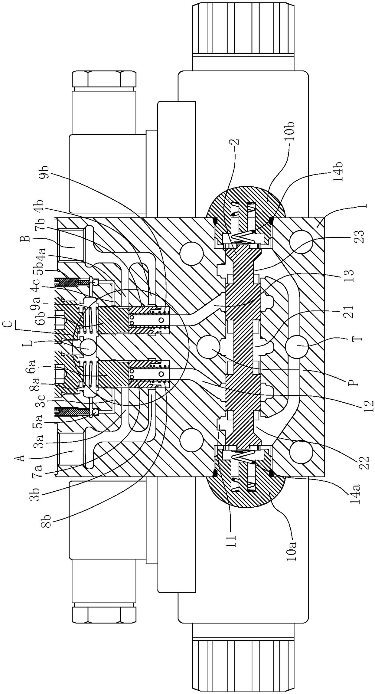
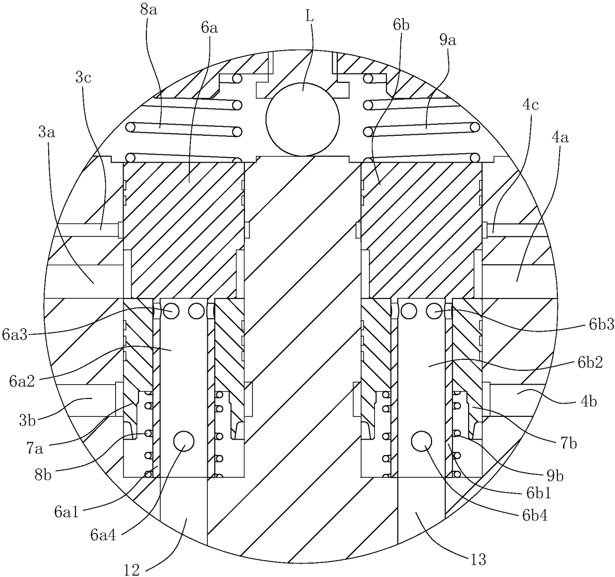
[0018] Such as figure 1 , 2 Shown is a preferred embodiment of the present invention.

[0019] A compact solenoid proportional valve comprising

[0020]A valve block 1 having a transverse shaft hole 11, a left vertical shaft hole 12 and a right vertical shaft hole 13, the left vertical shaft hole 12 and the right vertical shaft hole 13 are located above the transverse shaft hole 11 and respectively connected to the transverse shaft hole 11 Connected, the valve block 1 is provided with a pressure oil port P, a first working oil port A, a second working oil port B, an oil return port T and a load pressure feedback port L, wherein the pressure oil port P communicates with the transverse shaft hole 11 And located between the left vertical shaft hole 12 and the right vertical shaft hole 13, the oil return port T is respectively connected to the ...


PUM


Abstract

The invention relates to a compact electromagnetic proportion valve. The compact electromagnetic proportion valve is characterized by comprising a valve block, a reversing valve core, a left pressurecompensation valve core, a left one-way valve bush, a right pressure compensation valve core and a right one-way valve bush, wherein the valve block comprises a transverse shaft hole, a left verticalshaft hole, a right vertical shaft hole, a pressure oil port, a first working oil port, a second working oil port, an oil return port and a loading pressure feedback port; the reversing valve core isdriven by an electromagnetic driving structure to slide left and right, and a middle through-flow groove, a left through-flow groove and a right through-flow groove which are annular are formed in theperiphery of the reversing valve core; the left pressure compensation valve core and the left one-way valve bush are arranged in the left vertical shaft hole and can slide up and down; and the rightpressure compensation valve core and the right one-way valve bush are arranged in the right vertical shaft hole and can slide up and down. The compact electromagnetic proportion valve has a flow saturation resistance function; multiple hydraulic valves are integrated in one valve block; the compact electromagnetic proportion valve comprises few oil passages which are regularly arranged, thus facilitating processing; meanwhile, the compact electromagnetic proportion valve is relatively compact in structure and convenient to disassemble and assemble; each valve core stably moves; the operation performance of a vehicle or engineering machinery using the valve is greatly improved; and the phenomena such as excessive fasting under a low load and stopping under a high load are avoided.

Description

technical field [0001] The invention belongs to the technical field of hydraulic valves, and in particular relates to a compact electromagnetic proportional valve used in hydraulic systems of various engineering machinery, agricultural machinery, mining machinery and forestry machinery. Background technique [0002] Flow saturation refers to the flow saturation state caused when the maximum flow that the pump can provide cannot meet the needs of the system. In the case of compound action of the multi-way valve, multiple actuators act at the same time, and the total flow required increases. If the pump cannot provide sufficient flow, the system cannot complete the compound action, which seriously affects the operation quality and efficiency. Anti-flow saturation means that when the system is in the state of flow saturation, the flow of each actuator is reduced at the same time, so that the total flow of the system matches the flow that the pump can provide, and the compound a...

Claims


Application Information

Patent Timeline
Patent Type & Authority Applications(China)
IPC IPC(8): F15B13/02F16K31/06
CPCF15B13/02F16K31/0603
Inventor 邵立坤
Owner 江苏南京国家农业高新技术产业示范区发展集团有限公司
Learn More