
Lock pin type synchronizer

A technology of synchronizer and synchronizing ring, applied in the direction of clutch, mechanical drive clutch, mechanical equipment, etc., can solve the problems of inconvenient increase of synchronizer load, reduce production efficiency, short service life, etc., to improve load and service life, improve The effect of increasing production efficiency and increasing the number of installations

Pending Publication Date: 2018-09-14
SHIYAN TONGCHUANG DRIVE TECH CO LTD
View PDF10 Cites 0 Cited by
  • Summary
  • Abstract
  • Description
  • Claims
  • Application Information

AI Technical Summary

Problems solved by technology

[0003] 1. Since the sliding gear sleeve in the lock-pin synchronizer of the traditional structure is an integral structure, when processing the external spline, the external splines on both sides of the disc on the sliding gear sleeve must be processed separately, which greatly reduces the improved production efficiency;
[0004] 2. In the lock pin type synchronizer of the traditional structure, a locking boss on a synchronizing ring is correspondingly installed with a linkage long pin, and a locking boss on the other synchronizing ring is also correspondingly installed with a positioning short pin. pin, and is provided with a linkage hole, and equipped with a spring; this structure, because each synchronous ring needs to be provided with at least 3 locking bosses, and each locking boss must correspond to the disc on the sliding tooth sleeve A locking hole is designed on the top, so at least 6 locking holes need to be set on the disk part of the sliding tooth sleeve; in this way, when it is necessary to increase the number of locking bosses to reduce the number of single locking bosses and linkage long pins and When the force of the positioning short pin is applied, every time one locking boss is added to the two synchronous rings, two corresponding locking holes need to be added on the disk part of the sliding tooth sleeve, which greatly limits the increase The number of locking bosses is not convenient to increase the load that the synchronizer can bear, and the service life is short

Method used


Image

  • Lock pin type synchronizer
  • Lock pin type synchronizer
  • Lock pin type synchronizer

Examples


Embodiment Construction

[0040] The present invention will be described in further detail below in conjunction with the accompanying drawings and embodiments, but these embodiments should not be construed as limiting the present invention.

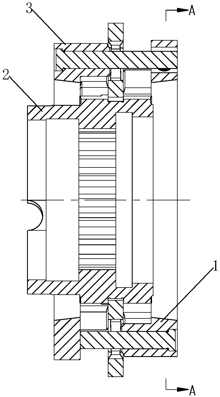
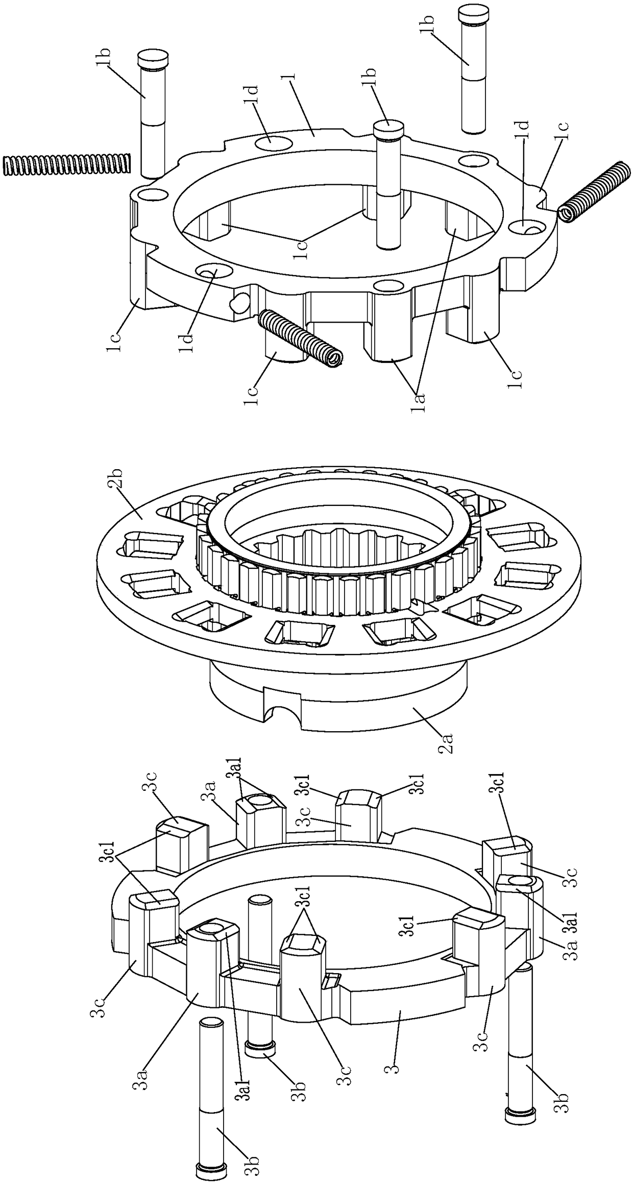
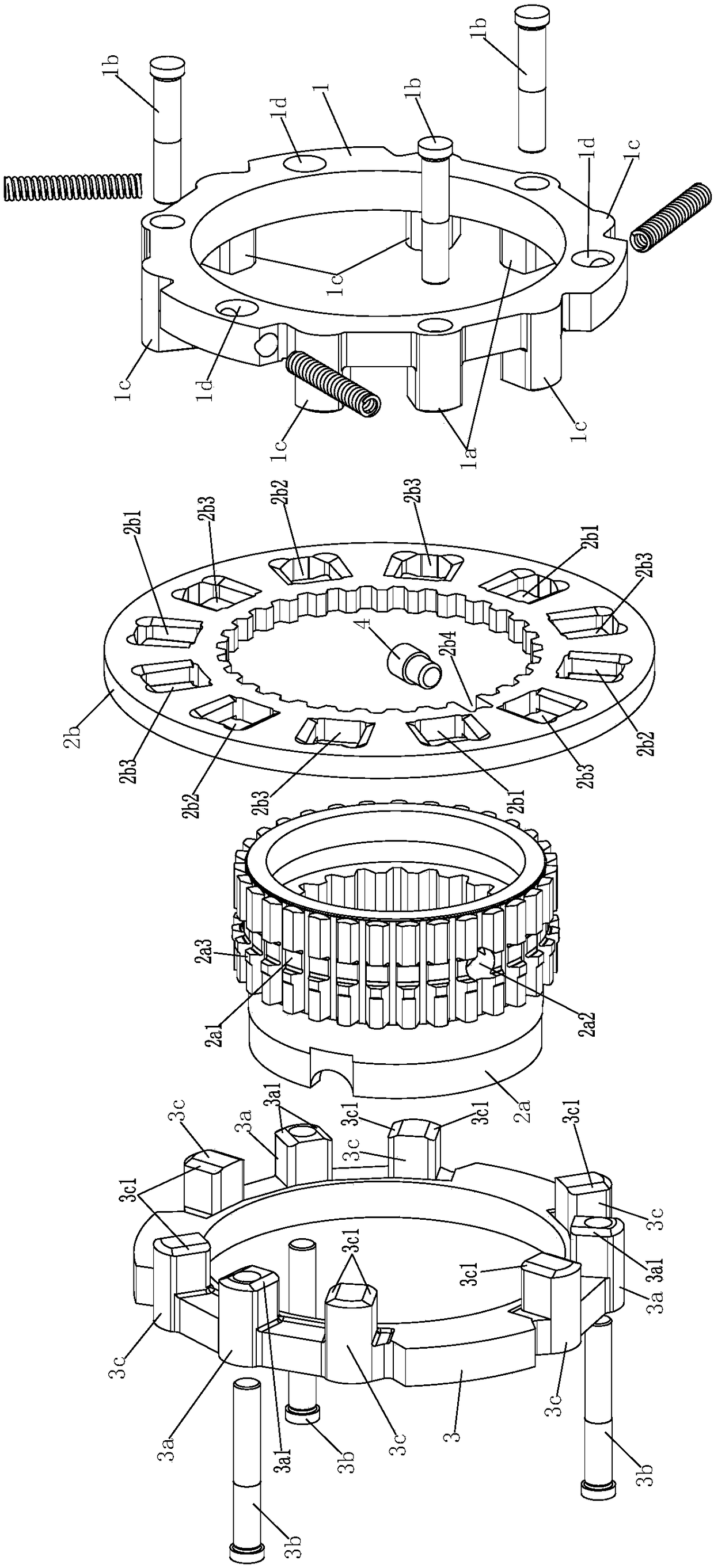
[0041] Such as figure 1 Shown: This embodiment provides a pin-type synchronizer, including: a first synchronous ring 1, a sliding tooth sleeve 2 and a second synchronous ring 3, the first synchronous ring 1 and the second synchronous ring 3 face One side of the sliding tooth sleeve 2 is respectively provided with a first locking boss 1a and a second locking boss 3a, and the first locking boss 1a and the second locking boss 3a are respectively The positioning short pin 1b and the linkage long pin 3b are correspondingly inserted. The sliding tooth sleeve 2 includes a spline sleeve 2a and a sliding plate 2b. Keys and spline sleeve outer splines, the inner wall of the slide plate 2b is provided with slide plate inner splines matching with the spline sleeve outer spli...


PUM


Abstract

A lock pin type synchronizer comprises a first synchronous ring with a first locking boss and a second synchronous ring with a second locking boss; a positioning short pin and a linkage long pin are installed in the first locking boss and the second locking boss correspondingly; a sliding tooth sleeve comprises a spline sleeve and a sliding disk installed on the spline sleeve in a sleeved manner;a spline sleeve inner spline and a spline sleeve outer spline are arranged on the inner wall and the outer wall of the spline sleeve correspondingly; a sliding disk inner spline is arranged on the inner wall of the sliding disk; a first locking hole and a second locking hole are formed in the sliding disk; a third locking boss is arranged on the first synchronous ring; a fourth locking boss is arranged on the second synchronous ring; a third locking hole is formed in the sliding disk; the positioning short pin penetrates the first locking hole and makes contact with the second synchronous ring; the linkage long pin penetrates the second locking hole and is inserted in a linkage hole of the first synchronous ring; the first locking boss and the first locking hole are in face contact and thesecond locking boss and the second locking hole are in face contact; and the third locking boss and the corresponding fourth locking boss are in face contact with two side end ports of the same thirdlocking hole correspondingly. The lock pin type synchronizer is suitable for transmissions.

Description

technical field [0001] The invention relates to a synchronizer, in particular to a latch type synchronizer. Background technique [0002] At present, pin-lock synchronizers are generally used in medium and heavy-duty trucks. The pin-lock synchronizers with traditional structures have the following problems in actual use: [0003] 1. Since the sliding gear sleeve in the lock-pin synchronizer of the traditional structure is an integral structure, when processing the external spline, the external splines on both sides of the disc on the sliding gear sleeve must be processed separately, which greatly reduces the improved production efficiency; [0004] 2. In the lock pin type synchronizer of the traditional structure, a locking boss on a synchronizing ring is correspondingly installed with a linkage long pin, and a locking boss on the other synchronizing ring is also correspondingly installed with a positioning short pin. pin, and is provided with a linkage hole, and equipped ...

Claims


Application Information

Patent Timeline
IPC IPC(8): F16D23/02
CPCF16D23/02F16D23/025
Inventor 田军杨宏伟刘刚吕小宝吴峰
Owner SHIYAN TONGCHUANG DRIVE TECH CO LTD
Learn More