Eureka AIR delivers breakthrough ideas for toughest innovation challenges, trusted by R&D personnel around the world.

Nuclear fuel assembly guiding tube

A nuclear fuel assembly and fuel assembly technology, applied in nuclear engineering, nuclear power generation, nuclear reaction control, etc., can solve the problems of difficult rolling process of guide tubes, increase of buffer pipes and end plugs, failure of fuel assembly skeleton, etc., and achieve improvement Manufacturing economy, increased rigidity, and high manufacturing economy

Inactive Publication Date: 2018-09-14
NUCLEAR POWER INSTITUTE OF CHINA
View PDF2 Cites 2 Cited by
  • Summary
  • Abstract
  • Description
  • Claims
  • Application Information

AI Technical Summary

Problems solved by technology

The structure of the MonoblocTM guide tube is simple, but the rolling process of the guide tube is relatively difficult, and this process has not yet been mastered in China; the AP1000 guide tube is a tube-in-tube structure, and the buffer tube is placed at the lower end of the guide tube, and the two are matched through their respective end plugs , but although the AP1000 guide tube avoids the difficult rolling process of the AFA3G guide tube, the buffer tube and end plug are added, the structure is more complicated, and the positioning and matching are more difficult
In addition, the AP1000 guide tube needs to be expanded with the bottom grid casing first, and then inserted into the internal buffer tube for expansion to form a guide tube component. There is a risk that the entire fuel assembly skeleton will fail due to the failure of the guide tube component expansion, and the expansion process is difficult. bigger

Method used


Image

  • Nuclear fuel assembly guiding tube
  • Nuclear fuel assembly guiding tube

Examples


Embodiment 1

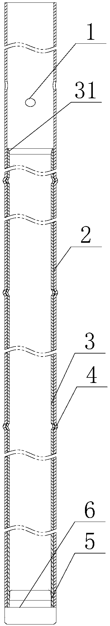
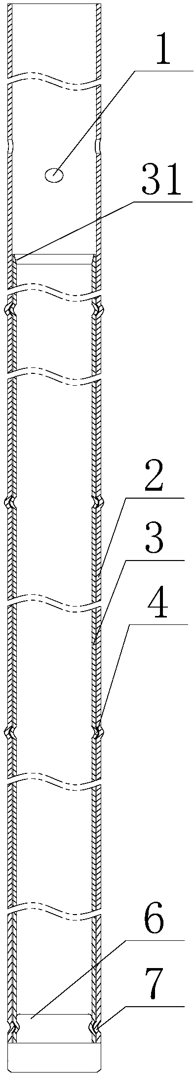
[0022] Such as Figure 1~2 As shown, this embodiment includes an outer tube 2 with both ends open, and an end plug 6 for sealing the lower end opening of the outer tube 2, at least one inner tube 3 is fixed on the inner peripheral wall of the outer tube 2, and the The lower end surface of the outer tube 2 is flush with the lower end surface of the inner tube 3 . In view of the complex structure of the guide tube in the prior art, the difficulty in positioning and matching after expansion, and the expansion part of the guide tube is prone to failure, which in turn leads to the failure of the skeleton of the entire fuel assembly. In this regard, the applicant abandoned the traditional guide tube design method , using a double-layer design of the outer tube 2 and the inner tube 3, and the lower end surface of the inner tube 3 is flush with the lower end surface of the outer tube 2 and then connected to the end plug 6, so as to meet the buffering effect required by the fuel assemb...

Embodiment 2

[0025] Such as Figure 1~2 As shown, in this embodiment, on the basis of Embodiment 1, the end plug 6 is fixed on the lower opening of the outer tube 2 by welding, and it is not limited to welding. Other fixing methods can be carried out according to specific conditions, as long as the end plug 6 is ensured. It only needs to be stably fixed at the opening of the lower end of the outer tube 2, that is, the connection point II5 is formed, and the outer tube 2 and the end plug 6 after welding or spinning form a complete composite guide tube, which consists of guide tube parts and grids, etc. Other components are assembled to obtain the fuel assembly skeleton, and expansion or welding failure only affects a single guide tube part, not the fuel assembly skeleton, which improves the manufacturing economy of the fuel assembly.

[0026] The inner tube 3 is fixed on the lower part of the inner wall of the outer tube 2 by welding or expansion, and is not limited to welding or expansion....

Embodiment 3

[0028]like Figure 1~2 As shown, in this embodiment, the lower opening of the outer tube 2 and the lower opening of the inner tube 3 are fixed on the end plug 6 by welding or spinning. The lower end of the outer tube 2 and the lower end of the inner tube 3 are fixed together with the end plug 6 by welding or spinning process, and a spinning groove is formed on the outer wall of the end plug 6, so that the outer tube 2, the inner tube 3 and the end plug 6 The guide tube part is formed, and the fuel assembly frame is obtained by assembling the guide tube part and other parts such as the grid. Expansion or welding failure only affects a single guide tube part and does not affect the fuel assembly frame, which improves the manufacturing economy of the fuel assembly.

[0029] As preferably, a chamfer 31 is provided on the inner peripheral wall of the upper end of the inner tube 3, so that the control rod plays a guiding role when it falls, and avoids the outer wall or the lower end...


PUM


Abstract

The invention discloses a nuclear fuel assembly guiding tube. The nuclear fuel assembly guiding tube comprises an outer tube and an end plug, wherein two ends of the outer tube are open; the end plugis used for sealing the opening of the lower end of the outer tube; at least one inner tube is fixed on the inner peripheral wall of the outer tube; and the lower end surface of the outer tube is parallel and level to the lower end surface of the inner tube. For solving the problems that in the prior art, a guiding tube is complicated in structure, positioning fit difficulty is high after expansion, an expansion portion of the guiding tube fails easily, and thus, the framework of a whole fuel assembly fails, a traditional guiding tube designing mode is abandoned, double-layered design of an outer tube and an inner tube is adopted, after being parallel and level to the lower end surface of the outer tube, the lower end surface of the inner tube is connected with the end plug so as to achieve the buffering effect which meets the requirement for the fuel assembly, sufficient rigidity of the guiding tube is ensured, and then the anti-seismic property of the nuclear fuel assembly guiding tube is improved.

Description

technical field [0001] The invention relates to the technical field of nuclear reactor fuel assemblies, in particular to a nuclear fuel assembly guide pipe. Background technique [0002] The nuclear fuel assembly is composed of a number of fuel rods, guide tube parts, positioning grids, upper and lower tube seats, etc. The guide tube part is the load-bearing part of the fuel assembly skeleton, and its basic functions are as follows: provide continuity for the fuel assembly structure; provide insertion channels for fuel-related components; provide hydraulic buffer for the drop of control rods during reactor emergency shutdown; provide fuel-related component rods Provides coolant flow. [0003] At present, the typical guide tube structures of PWR fuel assemblies mainly include AFA3G guide tube and AP1000 guide tube). The AFA3G guide tube is a MonoblocTM guide tube, which adopts the design of increased wall thickness of the buffer section, the outer diameter of the guide tube...

Claims


Application Information

Patent Timeline
Patent Type & Authority Applications(China)
IPC IPC(8): G21C7/20G21C7/08
CPCG21C7/08G21C7/20Y02E30/30
Inventor 朱发文茹俊陈平肖忠李庆王坤雷涛焦拥军李云张林张坤蒲曾坪高士鑫
Owner NUCLEAR POWER INSTITUTE OF CHINA
Why Eureka
Eureka Blog
Learn More