Eureka AIR delivers breakthrough ideas for toughest innovation challenges, trusted by R&D personnel around the world.

Multiple-head friction welding method

A friction welding, multi-head technology, applied in welding equipment, non-electric welding equipment, household components, etc., can solve the problems of long time, labor and time required for melting, joining and hardening, and improve the production economy and simplicity. Welding, the effect of shortening the processing time

Inactive Publication Date: 2004-06-16
MULTI ORBITAL SYST
View PDF3 Cites 0 Cited by
  • Summary
  • Abstract
  • Description
  • Claims
  • Application Information

AI Technical Summary

Problems solved by technology

Disadvantages of this multi-head pressure butt welding are in particular the excessively long processing times, i.e. the time required for melting, joining and hardening
Since the heat of machining can only be lost slowly from the weld seam, the large unavoidable weld flash formed during machining can only be removed by cutting after a few minutes, especially in the inner part and the corner section The cutting process is very labor-intensive and time-consuming
Such multi-head-pressurized butt welding equipment requires a lot of energy because the welding mirror must be continuously kept at the welding temperature even when welding is not being performed
Moreover, an oxide skin will be formed on the surface of the mirror, so this layer of oxide skin must be eliminated. For this reason, a mirror protective coating made of polytetrafluoroethylene must usually be used, which increases the production cost.

Method used


Image

  • Multiple-head friction welding method
  • Multiple-head friction welding method
  • Multiple-head friction welding method

Examples


Embodiment Construction

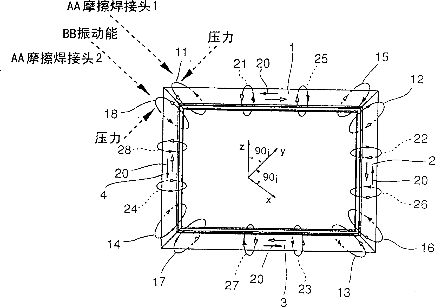
[0027] figure 1 Shows a polygonal frame with four profiled bars 1, 2, 3 and 4, said profiled bars are connected to each other on joint surfaces extending at 45° in the longitudinal direction, and the working principle of the present invention is shown in the figure .

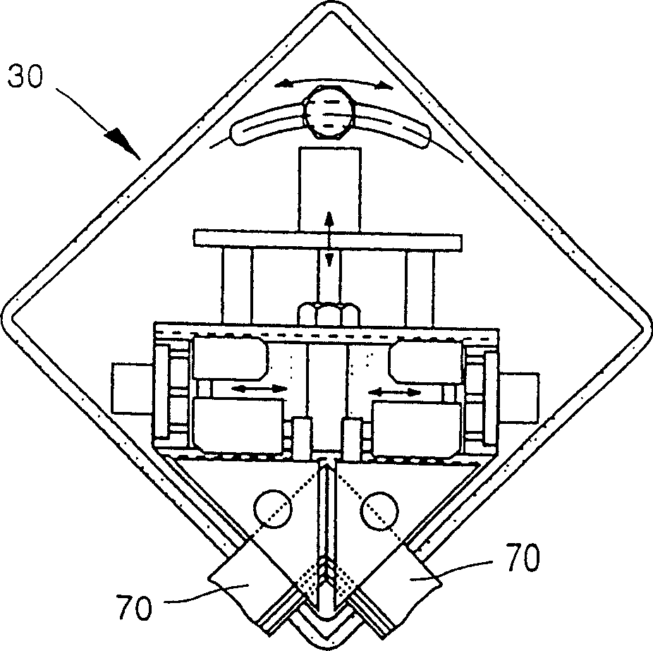
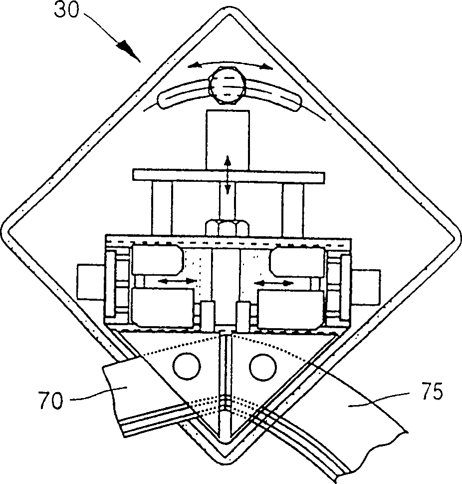
[0028] Vibration energy added to achieve the friction welding joint is applied to the corner sections to be welded by means of a friction welding unit 30 with two friction welding heads 44 exemplified below. For this purpose, each friction welding joint 44 has a clamping unit 64 with which the profiled rod end is fixed and vibration energy is applied to this end. The arrangement of the two friction welding heads 44 in the friction welding unit 30 is such that the joint surfaces on the joint plane are pressed against each other. Utilize the friction welding head 44 to make the special-shaped rods 1, 2, 3 and 4 ends clamped in the clamping unit 64 vibrate on both sides of the joint plane, so that the joint plane...


PUM


Abstract

The aim of the invention is to produce mitre-welded profiles (1,2,3,4) or profile frames. A friction welding unit is used for the friction welding joining. Open and closed frame profiles can be produced by means of said unit. In a special embodiment, all mitre joints are simultaneously produced in a very short cycle time and with very low welding waste in a multiple-head friction welding device.

Description

technical field [0001] The invention relates to a multi-head-friction welding method for simultaneously welding joint surfaces of open or closed special-shaped frames. Background technique [0002] Friction welding is known as a method in which friction is generated by relative movement and simultaneous pressurization, generating the necessary fusion energy on the surfaces to be welded. This is primarily linearly and rotationally symmetrical welding, which is not suitable for welding asymmetrical bodies such as profiled rods for window and door frames. [0003] Currently, it is common practice in the production of window and door frames from plastic profiles to join the beveled joint surfaces by means of mirror welding (DE-A-41 18 258). Simultaneous welding of the bevels of such profiled frames with a welding mirror is known as pressurized butt welding, wherein the welding mirrors are used to melt the joint surfaces and after removal of the welding mirror, the joint surface...

Claims


Application Information

Patent Timeline
Patent Type & Authority Patents(China)
IPC IPC(8): B23K20/12B29C65/00B29C65/06B29C65/78B29L31/10
CPCB29C66/1162B29C66/91B29C66/90B23K20/129B29C65/0627B29C65/0618B29C65/0636B29C66/92B29C66/949B29C66/94B29L2031/005B29C66/5243B29C66/52431B29C66/843B29C66/9261B29C66/71B29C66/9513B29C65/7802B29C65/7841B29C66/73921B29C66/9517B29C66/81463B29K2027/06B29C65/06
Inventor 莱昂哈德·克拉塞尔
Owner MULTI ORBITAL SYST
Why Eureka
Eureka Blog
Learn More