Eureka AIR delivers breakthrough ideas for toughest innovation challenges, trusted by R&D personnel around the world.

Multi-frequency base station antenna and antenna feed system

A base station antenna and high-frequency technology, which is applied in the field of multi-frequency base station antenna and antenna feeder system, can solve the problems of large overall thickness and weight of the antenna, large medium thickness, and enlarged overall size of the antenna, etc., to reduce unfavorable coupling and improve radiation Direction pattern, the effect of maintaining high and low frequency radiation performance

Pending Publication Date: 2018-09-14
南京澳博阳射频技术有限公司
View PDF0 Cites 12 Cited by
  • Summary
  • Abstract
  • Description
  • Claims
  • Application Information

AI Technical Summary

Problems solved by technology

For the former method, the overall size of the antenna will become larger; for the latter method, it will only have a significant effect when the size of the medium reaches a certain multiple of the working wavelength of the high and low frequency radiation oscillator. Generally, the size of the medium needs to be high 0.1 to 0.25 times the operating wavelength of the frequency oscillator
For ultra-broadband high-frequency bands, such as 1710-2690MHz, according to the shortest wavelength of 111mm, the thickness of the medium is required to be about 11-27mm. In this way, the thickness of the medium will be larger, resulting in a larger overall thickness and weight of the antenna.

Method used


Image

  • Multi-frequency base station antenna and antenna feed system
  • Multi-frequency base station antenna and antenna feed system
  • Multi-frequency base station antenna and antenna feed system

Examples


Embodiment 1

[0035] An embodiment of the present invention provides a multi-frequency base station antenna. The multi-frequency base station antenna includes a reflector, at least one high-frequency radiation array, and at least one low-frequency radiation array. Wherein, the high-frequency radiation array and the low-frequency radiation array are arranged in parallel on the reflector.

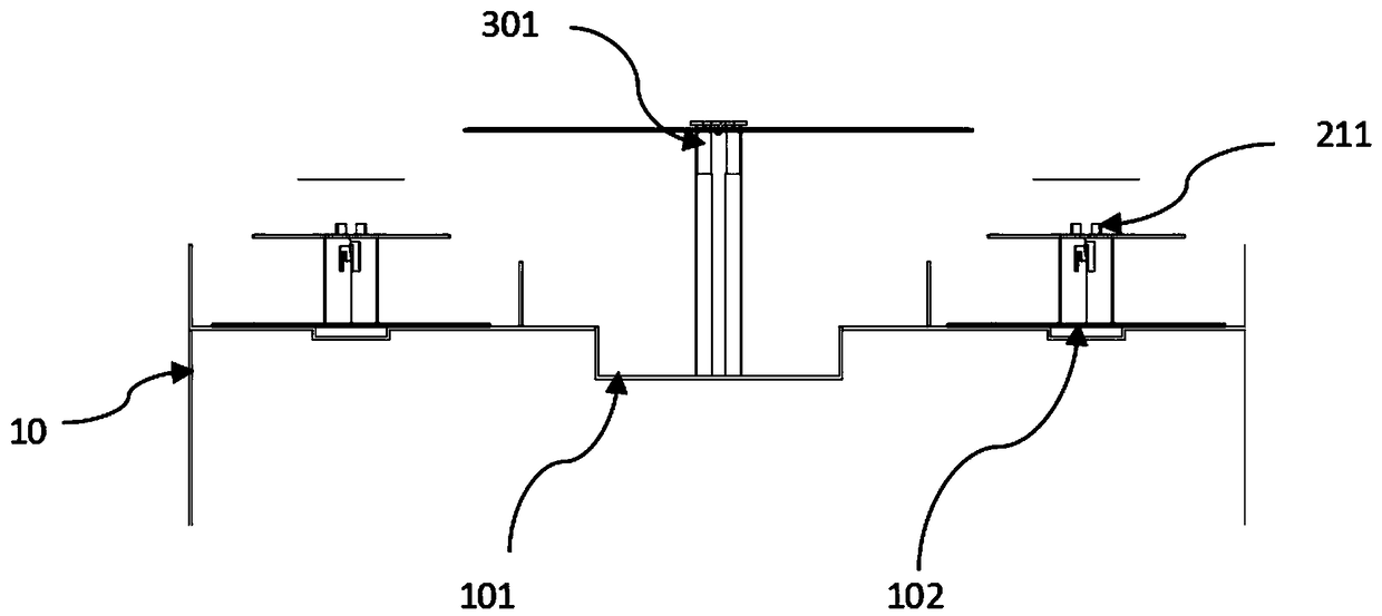
[0036]In the multi-frequency base station antenna, its high-frequency radiation array includes a plurality of high-frequency radiation units, and a gap is provided between the high-frequency radiation units and the reflection plate. The gap makes the connection between the high-frequency radiation unit and the reflector different from the traditional antenna design. In actual operation, the design of the gap can effectively eliminate the mutual coupling between the high-frequency radiation unit and the low-frequency radiation unit. Here, the structural design of the gap has at least the following two forms...

Embodiment 2

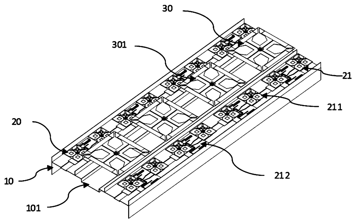
[0043] see figure 1 , a schematic diagram of a three-dimensional structure of a multi-frequency base station antenna provided for the introduction of an embodiment of the present invention, the multi-frequency base station antenna includes a reflector 10, a first high-frequency radiation array 20, a second high-frequency radiation array 21, and a low-frequency radiation array 30 . Wherein, the low-frequency radiation array 30 is arranged between the first high-frequency radiation array 20 and the second high-frequency radiation array 21 , and the three are arranged on the reflection plate 10 parallel to each other. Moreover, each high-frequency radiation array contains a plurality of high-frequency radiation units 211, and each high-frequency radiation unit 211 is also connected to a feed circuit 212, and the high-frequency radiation unit 211 and the feed circuit 212 together form a high-frequency array subassembly , the structure of the high-frequency array subassembly is as...

Embodiment 3

[0050] The embodiment of the present invention also provides an antenna feeder system, such as Figure 5 As shown, the antenna feeder system includes a feeder 52 and the multi-frequency base station antenna 51 provided in the first embodiment, the second embodiment and one of their possible implementations; the feeder 52 is connected to the multi-frequency base station antenna 51 .


PUM


Abstract

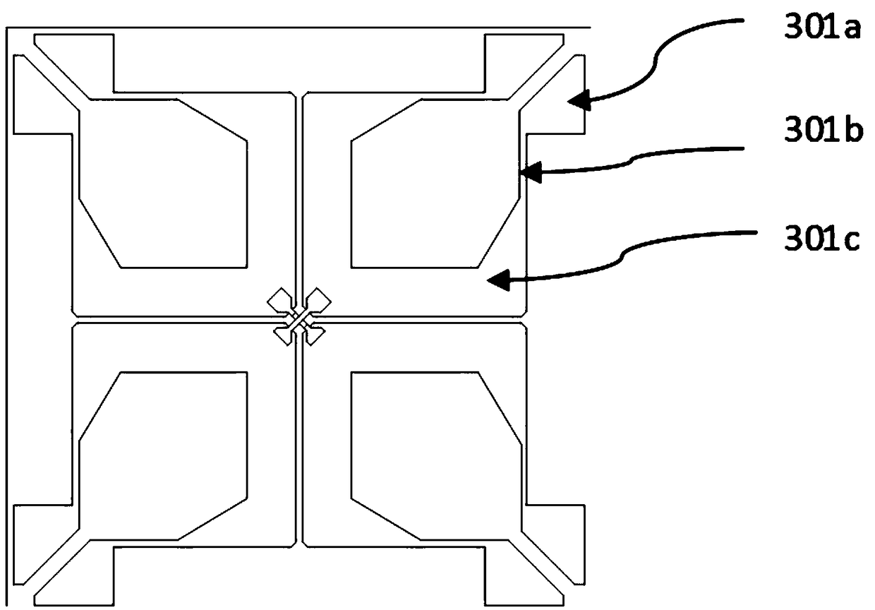
The invention provides a multi-frequency base station antenna and an antenna feed system, and relates to the technical field of communication. The multi-frequency base station antenna comprises a reflecting plate, at least one high frequency radiation array and at least one low frequency radiation array; the high and low frequency radiation arrays are arranged on the reflecting plate in parallel;each high frequency radiation array comprises high frequency radiation units, and slits exist are arranged between the high frequency radiation units and the reflecting plate; the low frequency radiation array comprise low frequency radiation units, and a radiation arm of each low frequency radiation unit includes a structure whose shape is similar to that of the Chinese character chuan (which means string); and the structure includes two wide end portions and a narrow intermediate portion. According to the multi-frequency base station antenna and antenna feed system, unfavorable coupling between the high and low frequency radiation units can be weakened, high and low radiation performances are maintained, and a radiation directional diagram of the high and low frequency arrays can be improved without increase of the overall size and thickness of the antenna.

Description

technical field [0001] The invention relates to the technical field of communication, in particular to a multi-frequency base station antenna and an antenna feeder system. Background technique [0002] Due to the shortage of base station site space resources, the miniaturization, multi-system, and broadband of multi-frequency base station antennas have become the mainstream of development. It is required that a pair of ultra-wideband multi-band base station antennas can work in multiple frequency bands, for example, one low-frequency radiation unit works in the 690-960MHz frequency band, and another or more high-frequency radiation units work in the 1710-2690MHz frequency band. The layout of the internal components of the multi-frequency base station antenna is becoming more and more compact, and two or more groups of radiating oscillator units working at different frequencies are getting closer to reduce the volume of the base station antenna. However, the spatial mutual co...

Claims


Application Information

Patent Timeline
IPC IPC(8): H01Q1/24H01Q1/36H01Q1/50H01Q19/10
CPCH01Q1/246H01Q1/36H01Q1/50H01Q19/10
Inventor 卜安涛苏学伟王攀峰徐腊平王徐军
Owner 南京澳博阳射频技术有限公司
Why Eureka
Eureka Blog
Learn More