Cable damage point detection and repair device and method

A technology for damaged points and cables, which is used in insulation/armored cable repair equipment, optical testing flaws/defects, etc. It can solve the problems of complex structure, heavy workload, and hidden safety hazards, and achieve simple repair structure, convenient and simple efficiency, and high efficiency. The effect of strong stability

Inactive Publication Date: 2018-09-14
SOUTHWEST UNIVERSITY
View PDF7 Cites 13 Cited by
  • Summary
  • Abstract
  • Description
  • Claims
  • Application Information

AI Technical Summary

Problems solved by technology

However, the device cannot work online, and the cable needs to be cut off from the line for repair, which has a large workload and wastes manpower, material resources and financial resources
In addition, this device can only realize the repair of the cable, but cannot solve the problem of online fault det

Method used


Image

  • Cable damage point detection and repair device and method
  • Cable damage point detection and repair device and method
  • Cable damage point detection and repair device and method

Examples


Embodiment Construction

[0054] The present invention will be further described below in conjunction with accompanying drawing.

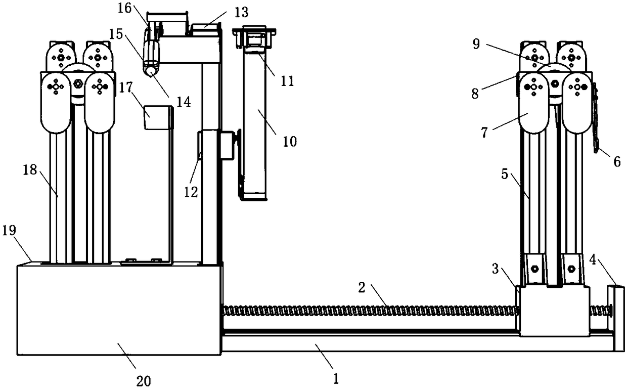
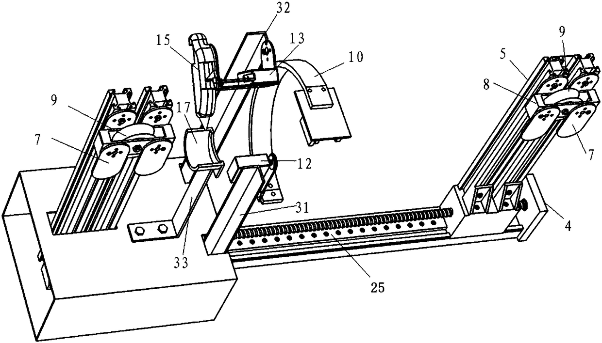
[0055] The cable damage point detection and repair device of the present invention includes a base component, a transmission component, a traveling component, a packaging box, a detection component, a repair component and a control circuit.

[0056] Such as figure 1 , image 3 and Figure 4 As shown, the base assembly includes a base 1, a linear guide rail 25, a front support block 4 and a rear support block 28, the linear guide rail 25 is horizontally arranged on the base 1, and the front support block 4 and the rear support block 28 are respectively fixed on the bottom of the base 1. Front and rear ends. In this example, the linear guide rail 25 is fixed above the base 1 by a plurality of countersunk screws. The front support block 4 is located at the front end of the device, and the front support block 4 is fixed on the front side of the base 1 by countersunk screws....


PUM


Abstract

The invention discloses a cable damage point detection and repair device and method. The device comprises a base assembly, a transmission assembly, a walking assembly, a packaging box, a detection assembly, a repair assembly and a control circuit. Through the cooperation of front pulley components, rear pulley components and locking components in the walking assembly, the moving manner of advancing on a cable is higher in stability compared with conventional pulleys; the device has an online autonomous detection function for cable damage points, and is more efficient, more convenient, simplerand safer compared with artificial detection; the device has an online repair function for the cable damage points, and is simple in repair structure and convenient to operate, so that the disadvantages of risk and low efficiency caused by traditional cable climbing of workers are replaced.

Description

technical field [0001] The invention belongs to the technical field of robot intelligent control, and in particular relates to a device and method for detecting and repairing cable damage points. Background technique [0002] Cables are mainly used for power transmission and distribution, and are mainly composed of four main structures: wires, insulation layers, shielding layers, and outer protective sheaths. Among them, the wire is used for the transmission of current or electromagnetic wave information; the insulating layer is coated on the outside of the wire to provide electrical insulation; the shielding layer is used to isolate the electromagnetic field in the cable from the external electromagnetic field; the outer protective sleeve is to protect the insulating layer. effect. Once the outer sheath is damaged, the wires, insulating layer and shielding layer are also prone to failure under external influences. Therefore, the outer protective sheath plays a protective r...

Claims


Application Information

Patent Timeline
IPC IPC(8): H02G1/16G01N21/88
CPCG01N21/88H02G1/16
Inventor 丁珠玉樊利张浪浪全胜冉代其
Owner SOUTHWEST UNIVERSITY
Why Eureka
Try Eureka