Explosion-proof electrical cabinet convenient for ventilation and heat radiation

A technology for ventilation and heat dissipation, electrical cabinet, applied in cooling/ventilation/heating transformation, electrical equipment shell/cabinet/drawer, electrical components, etc. Use and other problems, to achieve the effect of convenient connection, easy use, easy installation and disassembly

Inactive Publication Date: 2018-09-14
HEFEI DEJIE ENERGY CONSERVATION & ENVIRONMENTAL PROTECTION TECH CO LTD
View PDF0 Cites 2 Cited by
  • Summary
  • Abstract
  • Description
  • Claims
  • Application Information

AI Technical Summary

Problems solved by technology

[0003] The purpose of the present invention is to provide an explosion-proof electrical cabinet that is convenient for ventilation and heat dissipation, so as to solve the problem that the electrical cabinet cannot be ventilated and radiated, which may easily cause the inside of the electrical cabinet to be too high temperature, which will affect the use of the electrical cabinet. The wires inside the cabinet are inconvenient to arrange. When testing, it is easy to be messy and inconvenient for maintenance and use.

Method used


Image

  • Explosion-proof electrical cabinet convenient for ventilation and heat radiation
  • Explosion-proof electrical cabinet convenient for ventilation and heat radiation
  • Explosion-proof electrical cabinet convenient for ventilation and heat radiation

Examples


Embodiment 1

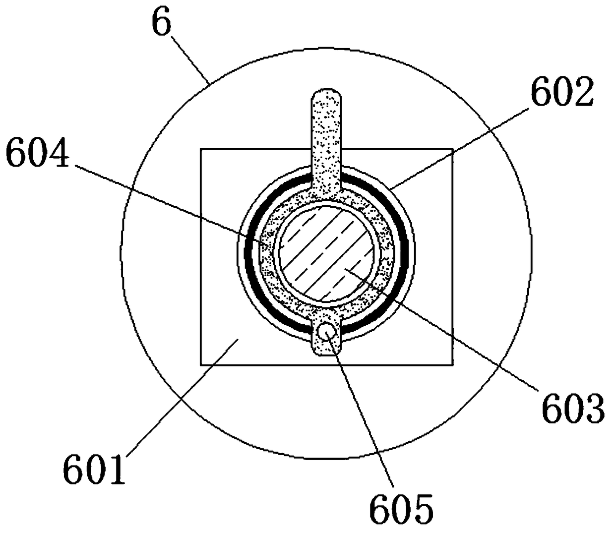
[0022] Example 1, such as image 3 The middle lead device 6 includes a first fixed block 601, a second fixed block 602, a limit rod 603, a pressing plate 604 and a hole 605, the first fixed block 601 is fixed with a second fixed block 602, and the inner side of the second fixed block 602 is arranged A limit rod 603, a pressure plate 604 is installed on the limit rod 603, a hole 605 is arranged on the pressure plate 604, the limit rod 603 runs through the inner side of the second fixed block 602, and the shape of the second fixed block 602 is a hollow cylinder, The shape of the limit rod 603 is a cylindrical structure, and the cross-sectional diameter of the limit rod 603 is equal to the diameter of the inner wall of the pressure plate 604, and the length of the pressure plate 604 is greater than the diameter of the second fixed block 602, which is convenient for winding the wires on On the limit rod 603, by pushing the pressing plate 604, it is convenient to squeeze the wires ...

Embodiment 2

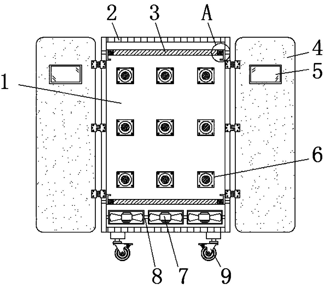
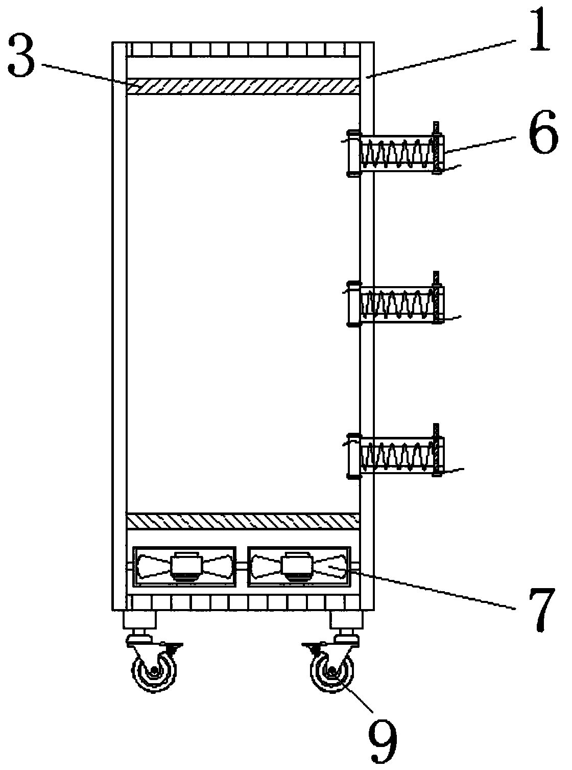
[0023] Example 2, such as Figure 5 The shape of the middle tie rod 11 is "L", and the pull rod 11 forms a telescopic structure through the spring 10 and the dust-proof net 3, and the distance between the pull rod 11 and the dust-proof net 3 is larger than the length of the block 12, so that it is convenient to pass the pull rod 11 Squeeze the spring 10 to connect the dust-proof net 3 with the clamping block 12, so as to facilitate placing the dust-proof net 3 inside the cabinet body 1, then loosen the pull rod 11, and clamp the clamping block 12 with the cabinet body 1 Groove connection is convenient for installing the dust-proof net 3 on the cabinet body 1, which is convenient to use.

[0024] Working principle: When using the explosion-proof electrical cabinet that is convenient for ventilation and heat dissipation, first pull the pull rod 11, and then squeeze the pull rod 11 against the spring 10, so that the block 12 can be connected with the dust-proof net 3 through the ...


PUM


Abstract

The invention discloses an explosion-proof electrical cabinet convenient for ventilation and heat radiation. The explosion-proof electrical cabinet comprises a cabinet body, blowers and pull rods. Theupper and lower ends of the cabinet body are provided with ventilation ports, and the internal side of the cabinet body is provided with lead devices. The left and right sides of the cabinet body areprovided with cabinet doors, and the cabinet doors are provided with windows. The lower end of the cabinet body is provided with universal wheels, and clamp blocks are connected on the left and rightinternal side surfaces of the cabinet body. Clamp blocks are fixed on the external side of the pull rods, and springs are connected on the internal side of the pull rods. Dust screens are connected on the springs, and springs are connected on the left and right ends of the dust screens. The blowers are arranged on the internal side lower end of the cabinet body, and connecting blocks are connected on the left and right ends of the blowers. According to the explosion-proof electrical cabinet convenient for ventilation and heat radiation, arrangement and penetration of various electric wires can be facilitated so that connection and utilization can be facilitated, internal ventilation and heat radiation of the electrical cabinet can be facilitated, dustproof processing can also be facilitated and use is convenient.

Description

technical field [0001] The invention relates to the technical field of explosion-proof electric cabinets, in particular to an explosion-proof electric cabinet convenient for ventilation and heat dissipation. Background technique [0002] With the continuous development of the social economy, all walks of life are also making progress. Take the electrical cabinet as an example, the wires are installed inside to facilitate the connection of the wires with the outside world, but the electrical cabinet also has large and small Problems affect people's use. For example, the electrical cabinet is inconvenient for ventilation and heat dissipation. When used in summer, the temperature is too high, which is likely to cause safety accidents, and it is inconvenient to organize and store the internal wires. It is inconvenient to find in time during maintenance, which affects work. Efficiency, in order to solve the shortcomings and deficiencies of the electrical cabinets on the market, t...

Claims


Application Information

Patent Timeline
Patent Type & Authority Applications(China)
IPC IPC(8): H05K5/02H05K7/20
CPCH05K5/0213H05K5/0247H05K7/20172H05K7/20181
Inventor 卢世军
Owner HEFEI DEJIE ENERGY CONSERVATION & ENVIRONMENTAL PROTECTION TECH CO LTD
Why Eureka
Try Eureka