Machine head structure of multifunctional tube-tube full-position automatic TIG welding

A welding head, all-position technology, used in welding equipment, arc welding equipment, manufacturing tools, etc., can solve the problems of the welding head without a visual monitoring mechanism, inoperability, and poor stability of manual welding.

Active Publication Date: 2018-09-18
SOUTH CHINA UNIV OF TECH
View PDF7 Cites 7 Cited by
  • Summary
  • Abstract
  • Description
  • Claims
  • Application Information

AI Technical Summary

Problems solved by technology

And for the working conditions of complex pipe structure and small pipe spacing, manual welding cannot be operated in such a narrow space, the stability of manual welding is poor, and the efficiency is low, but the pipe-pipe all-position automatic TIG welding can solve this problem very well
However, there are still deficiencies in the pipe-pipe all-position welding heads at home and abroad: 1. The traditional welding head cannot adjust the angle of the welding torch at will. Welding requirements for tube-tube lap joints (insert joints); 2. Th

Method used


Image

  • Machine head structure of multifunctional tube-tube full-position automatic TIG welding
  • Machine head structure of multifunctional tube-tube full-position automatic TIG welding
  • Machine head structure of multifunctional tube-tube full-position automatic TIG welding

Examples


Embodiment Construction

[0021] In order to make the object, technical solution and advantages of the present invention clearer, the present invention will be further described in detail below in conjunction with the embodiments and accompanying drawings.

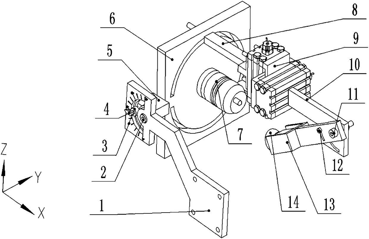
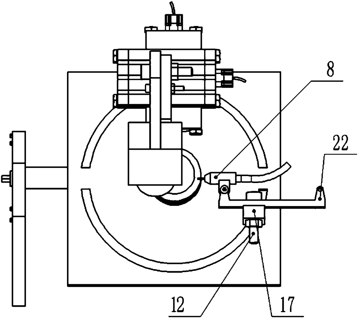
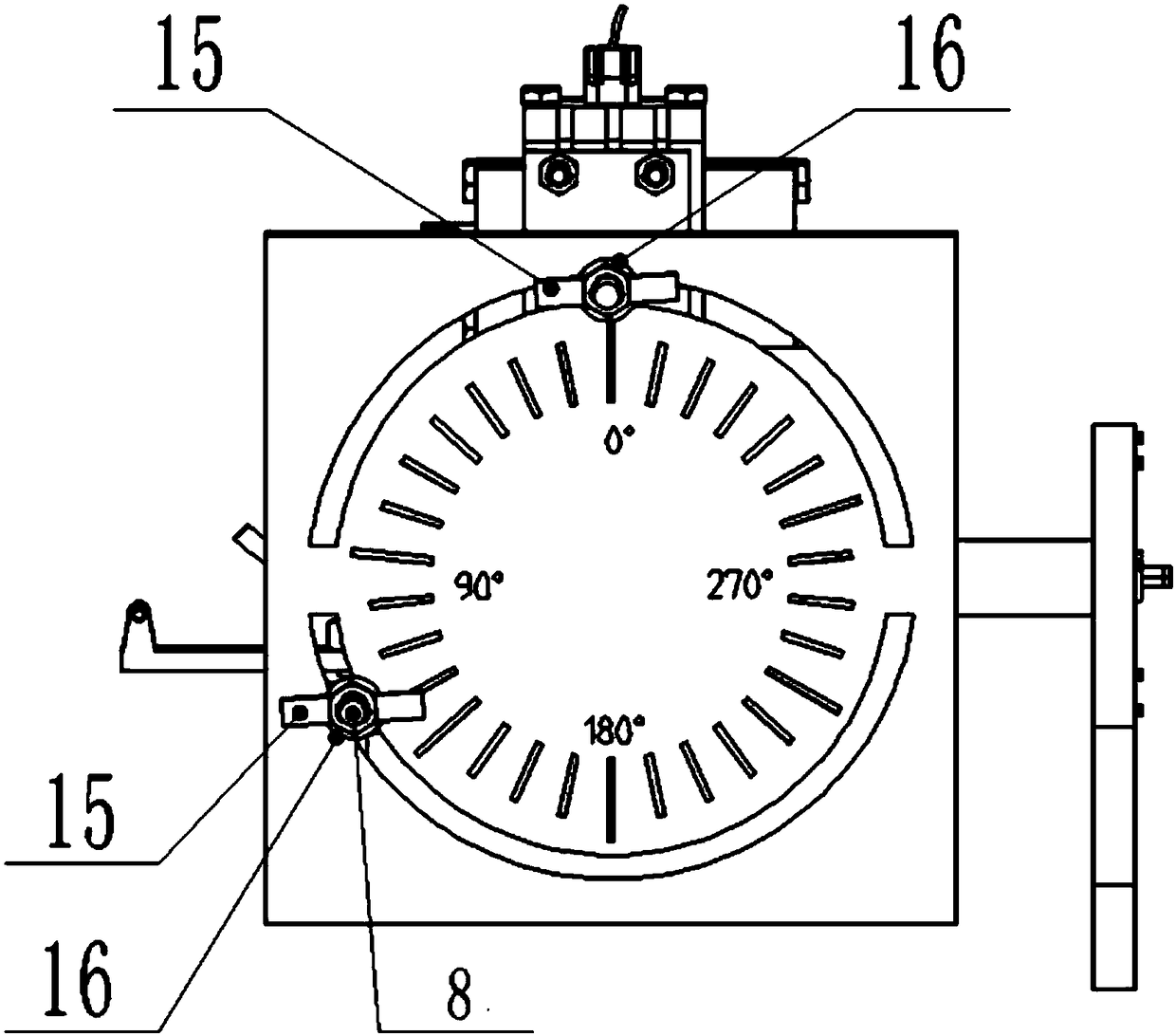
[0022] Such as Figure 1-Figure 6 As shown, it is the structure of multi-functional tube-tube all-position automatic TIG welding head, which is used for butt joint and lap joint (also called plug-in joint) of tube-tube full-position automatic TIG welding; including visual monitoring mechanism and welding torch angle adjustment Mechanism and wire feeding attitude adjustment mechanism; the torch angle adjustment mechanism and wire feeding attitude adjustment mechanism are respectively arranged on the left side and right side of the visual monitoring mechanism, and are respectively connected with the visual monitoring mechanism;

[0023] The arc track plate 6 of the visual monitoring mechanism, the connecting rod 8, the electric cross slide 9, the cam...


PUM


Abstract

The invention discloses a machine head structure of a multifunctional tube-tube full-position automatic TIG welding. The structure is used for butt joint and lap joint of the tube-tube full-position automatic TIG welding, the structure comprises a visual monitoring mechanism, a welding gun angle adjusting mechanism and a wire feeding posture adjusting mechanism, wherein the welding gun angle adjusting mechanism is arranged on the left side of the visual monitoring mechanism and the wire feeding posture adjusting mechanism is arranged on the right side of the visual monitoring mechanism, and the welding gun angle adjusting mechanism and the wire feeding posture adjusting mechanism are correspondingly connected with the visual monitoring mechanism; the visual monitoring mechanism comprises an arc rail plate, a connecting rod, an electric cross sliding block, a camera box and a lens protection cover; and the welding gun angle adjusting mechanism comprises a mounting frame, a rotating block, a pointer, the arc rail plate and a welding gun; the wire feeding posture adjusting mechanism comprises a wire feeding nozzle, a cross rail, the connecting rod and the arc rail plate. According tothe structure, the machine head structure of the multifunctional tube-tube full-position automatic TIG welding is suitable for the butt joint and the lap joint (inserting and connecting) of the tube-tube full-position automatic TIG welding are carried out, and the form of a root is not limited; the visual monitoring mechanism can clearly observes the condition of molten drop transition, so that the welding parameters, the welding gun angle and the wire feeding posture can be correspondingly adjusted; the optimized structure good in stability, the adjustment is simple, the design is simple andconvenient, and the tube-tube full-position automatic welding can be well realized.

Description

technical field [0001] The invention relates to the field of structural design of a welding torch head, in particular to a structure of a welding torch head applied to multi-functional pipe-pipe all-position automatic TIG welding. Background technique [0002] Pipe-pipe all-position automatic TIG welding means to keep the pipe horizontal and fixed, and the welding torch head goes around the pipe for welding, realizing single-sided welding and double-sided forming, which has the advantages of high welding efficiency, good welding quality and low cost. And for the working conditions of complex pipe structure and small pipe spacing, manual welding cannot be operated in such a narrow space, the stability of manual welding is poor, and the efficiency is low, but the pipe-pipe all-position automatic TIG welding can solve this problem well. However, there are still deficiencies in the pipe-pipe all-position welding heads at home and abroad: 1. The traditional welding head cannot ad...

Claims


Application Information

Patent Timeline
IPC IPC(8): B23K9/167B23K9/133B23K9/095B23K9/028
CPCB23K9/0282B23K9/0956B23K9/133B23K9/167
Inventor 石永华廖宝毅宁强
Owner SOUTH CHINA UNIV OF TECH
Why Eureka
Try Eureka