Outdoor charging pile for new energy vehicles

A technology of new energy vehicles and charging piles, which is applied in the direction of electric vehicle charging technology, charging stations, electric vehicles, etc., can solve the problems that affect the service life of electrical components inside the charging pile, the heat of the charging pile is difficult to discharge in time, and short-circuit fires, etc., to achieve Good heat dissipation effect, safety and filling guarantee, and the effect of avoiding dust accumulation

Inactive Publication Date: 2018-09-18
胡琼琼
View PDF0 Cites 14 Cited by
  • Summary
  • Abstract
  • Description
  • Claims
  • Application Information

AI Technical Summary

Problems solved by technology

At present, the charging piles specially provided for charging electric vehicles are composed of pile body, power cord, charging gun and electrical components installed inside the pile body. At present, in order to facilitate the charging of electric vehicles, most charging piles are installed outdoors. In order to avoid pile body The internal water enters and damages the electrical components. The pile body usually adopts a sealed structure, which makes it difficult to discharge the heat emitted by the electrical components inside the charging pile in time, resulting in the continuous high temperature inside the charging pile, which not only affects the internal electrical appliances of the charging pile. At the same time, it also makes the charging pile prone to short-circuit and fire during use, which has great potential safety hazards

Method used


Image

  • Outdoor charging pile for new energy vehicles
  • Outdoor charging pile for new energy vehicles
  • Outdoor charging pile for new energy vehicles

Examples


Embodiment Construction

[0025] The following will clearly and completely describe the technical solutions in the embodiments of the present invention with reference to the accompanying drawings in the embodiments of the present invention. Obviously, the described embodiments are only some, not all, embodiments of the present invention. Based on the embodiments of the present invention, all other embodiments obtained by persons of ordinary skill in the art without making creative efforts belong to the protection scope of the present invention.

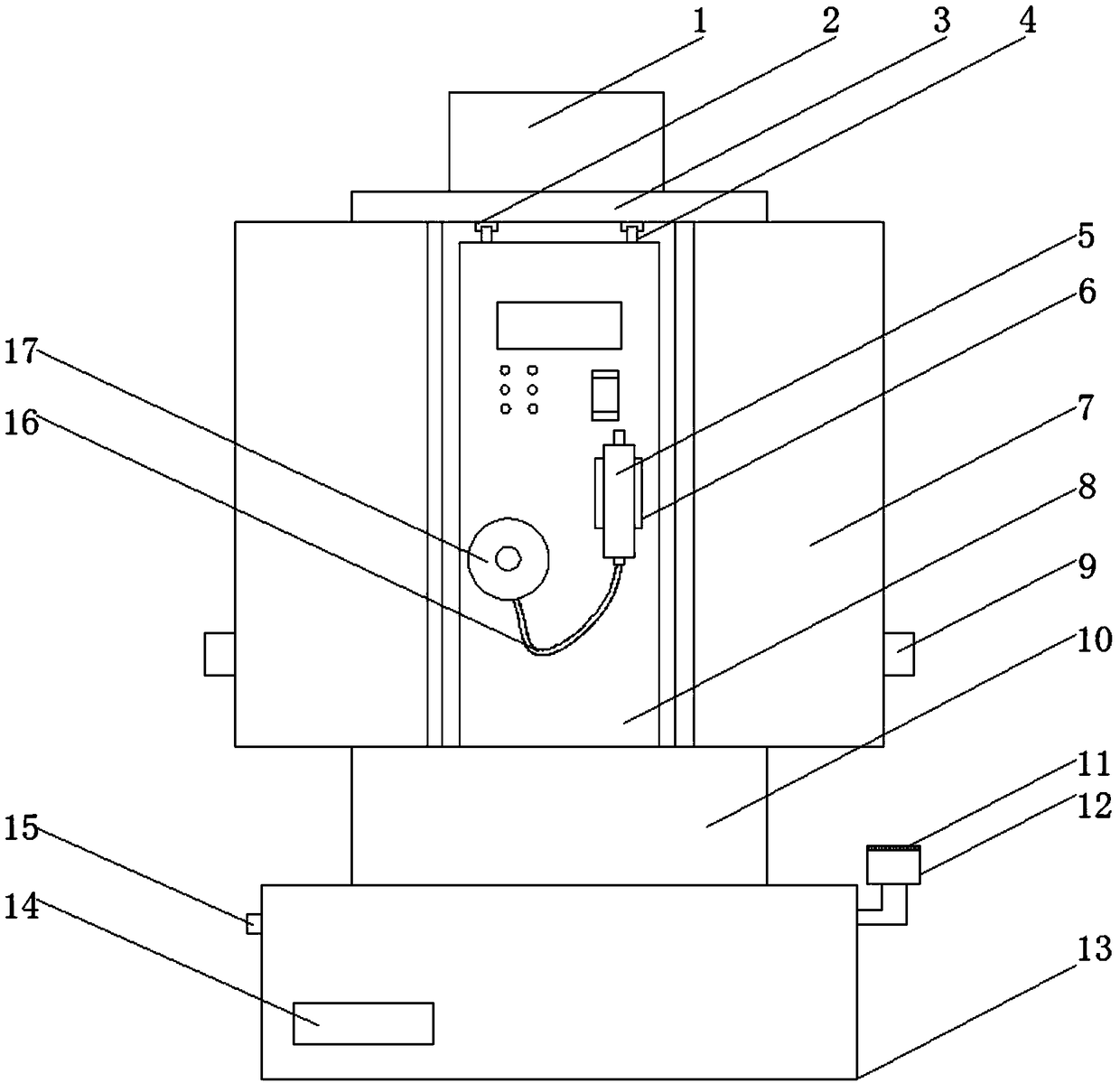
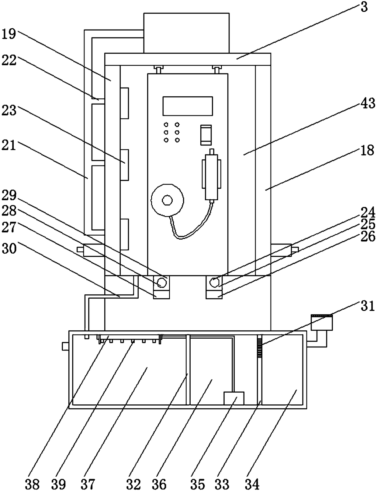
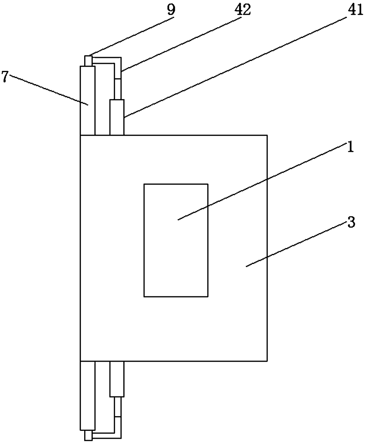
[0026] see Figure 1~6, in an embodiment of the present invention, an outdoor charging pile for new energy vehicles, including a fan 1, a guide chute 2, a top plate 3, a guide slider 4, a charging gun 5, a charging gun mounting frame 6, a sliding door 7, and a charging pile Main engine 8, connector 9, sliding base 10, filter screen plate 11, water receiving bucket 12, bottom box 13, airtight door 14, exhaust port 15, cable 16, reel 17, right side plate 18, lef...


PUM


Abstract

The invention discloses an outdoor charging pile for new energy vehicles. The outdoor charging pile comprises a fan, a sliding door, a charging pile main unit, a sliding base, a water receiving bucketand a bottom box, wherein the sliding base is fixedly mounted at the top of the bottom box; a left side plate is fixedly mounted at the left side of the top of the sliding base; a right side plate isfixedly mounted at the right side of the top of the sliding base; a rear end plate is fixedly mounted at the rear end of the top of the sliding base; the left side plate, the right side plate and therear end plate form a cavity; a top plate is fixedly mounted at the top of the cavity; the fan is fixedly mounted at the top of the top plate; the charging pile main unit is slidably mounted at the top of the sliding base; the charging pile main unit is positioned inside the cavity; and a winder and a charging gun mounting frame are fixedly mounted at the front end of the charging pile main unit.The outdoor charging pile for the new energy vehicles can prevent the charging pile main unit from being exposed so as to prolong the service life of the charging pile main unit, and has good heat dissipation, ventilation and dust removal functions so as to avoid dust accumulation of the charging pile main unit and provide a guarantee of safe charging for the new energy vehicles.

Description

technical field [0001] The invention relates to the field of new energy vehicles, in particular to an outdoor charging pile for new energy vehicles. Background technique [0002] In the current society, automobiles have become a common means of transportation for people. How to solve the contradictions between the increase in the number of automobiles and the energy crisis and environmental protection has become one of the major issues at present. New energy vehicles (mainly pure electric vehicles and hybrid vehicles) are an important direction of development in the next few years because of their energy saving, environmental protection and relatively mature technology. [0003] Electric vehicles need to charge the battery when the power of the power battery drops to a certain level. At present, the charging piles specially provided for charging electric vehicles are composed of pile body, power cord, charging gun and electrical components installed inside the pile body. A...

Claims


Application Information

Patent Timeline
Patent Type & Authority Applications(China)
IPC IPC(8): B60L11/18H05K7/20
CPCB60L53/31H05K7/20909Y02T10/70Y02T10/7072Y02T90/12
Inventor 彭小宝
Owner 胡琼琼
Why Eureka
Try Eureka