

Air fryer
An air fryer and pot body technology, which is applied to kitchen utensils, home utensils, roasters/barbecue grids, etc., can solve problems such as burns and burns on the pot body, and achieve the effect of safe and convenient use.
- Summary
- Abstract
- Description
- Claims
- Application Information
AI Technical Summary
Problems solved by technology
Method used
Image

Examples
Embodiment 1
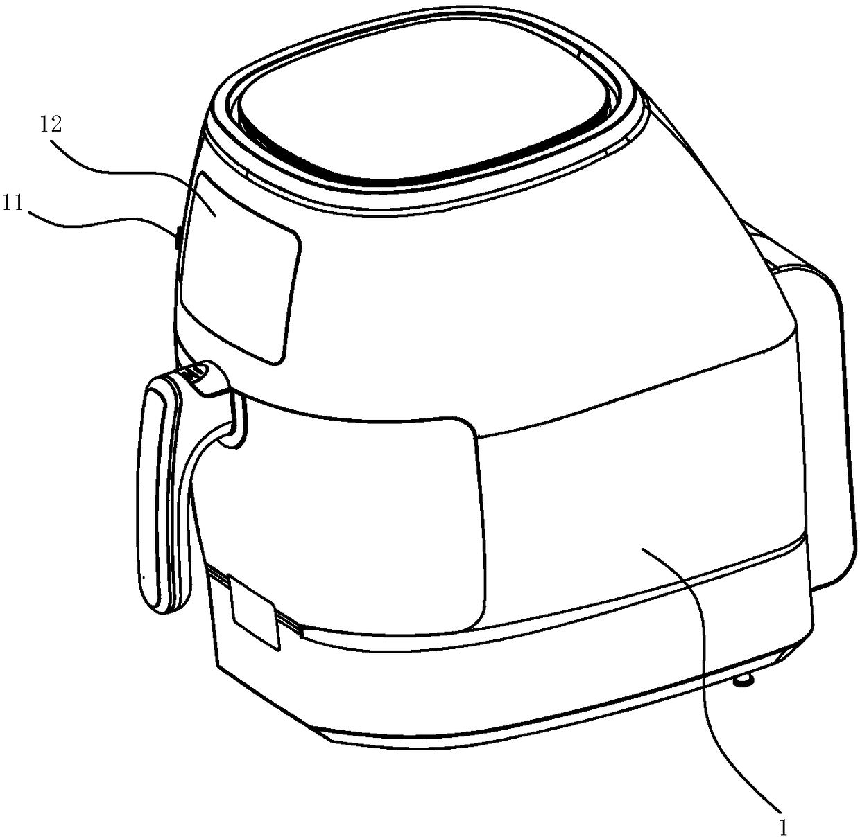
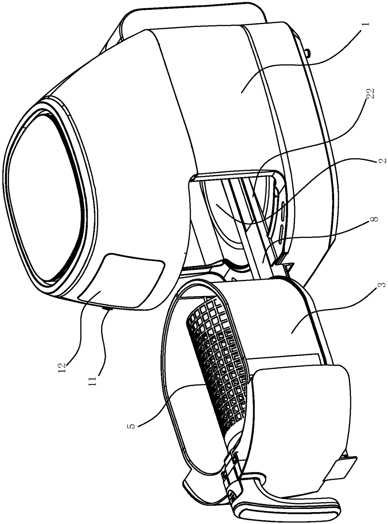
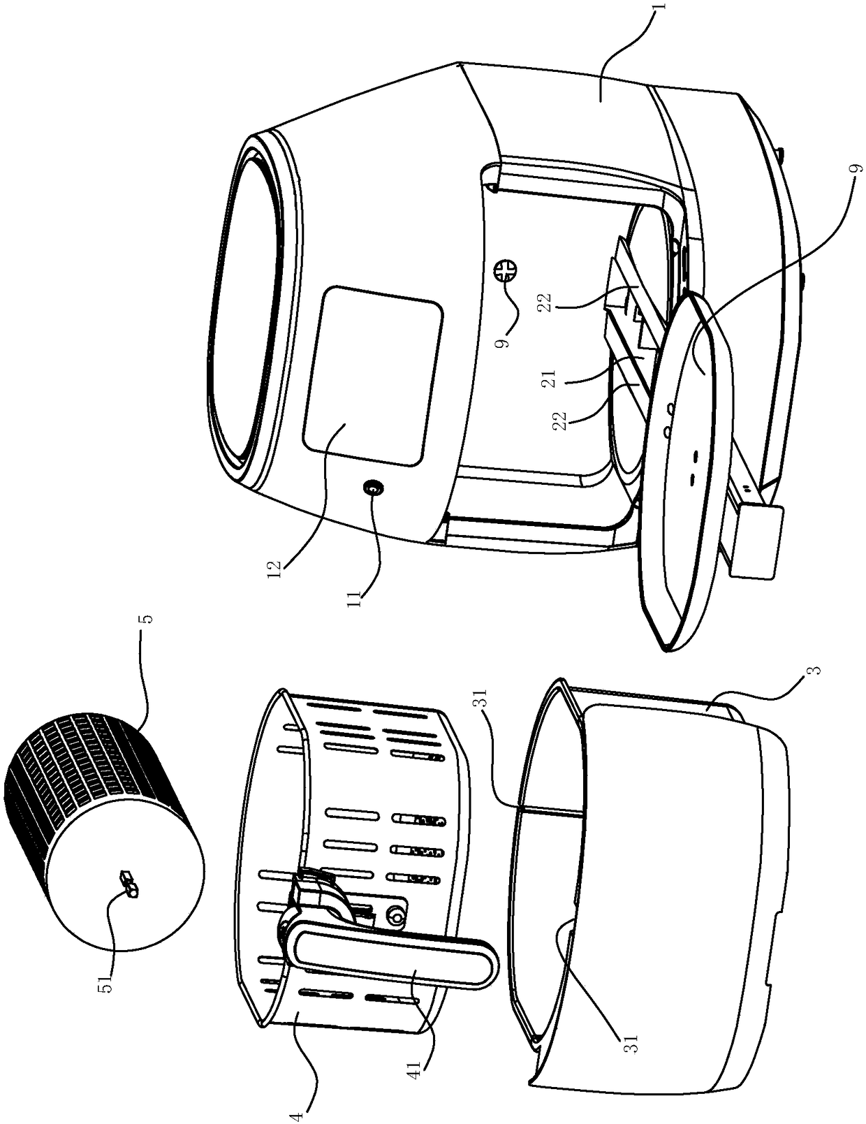
[0028] see Figure 1~6 The shown air fryer includes a body 1, a cooking cavity 2 with an opening is formed in the body 1, and the opening of the cooking cavity 2 is arranged on the front side of the body 1; The pot body 3, the inner pot 4 or / and the oven cage 5 can be placed in the pot body according to cooking needs. A handle can be provided on the outside of the pot body 3, and if no handle is provided on the outside of the pot body, a handle 41 can also be connected on the inner pot 4.
[0029] The body 1 is provided with a driving mechanism that can drive the pot body 3 to enter the cooking cavity from the opening of the cooking cavity 2 and can drive the pot body to move out of the cooking cavity from the opening of the cooking cavity. The connection is used to output the opening or closing command to the drive mechanism, so that the drive mechanism is activated and then drives the pot body to move out or enter the instruction input part of the cooking cavity. The input ...
Embodiment 2
[0035]The difference from Embodiment 1 is that the driving mechanism is an electric telescopic rod 10, and the electric telescopic rod 10 is arranged at the rear side of the cooking cavity. In this embodiment, the motor used by the electric telescopic rod can be connected to the drive shaft 23, and the rotary drive motor that can drive the drive shaft 23 to rotate can use the same motor. The electric telescopic rod 10 can also be replaced by a pneumatic telescopic rod, see Figure 7 shown.
Embodiment 3
[0037] Different from Embodiment 1, the opening of the cooking cavity 2 is arranged on the upper side of the body 1, and the upper part of the body includes a hot air assembly as a top cover, which is rotatably arranged on the body. The driving mechanism is an electric lifting rod 15 or a pneumatic lifting rod, and the pot body 3 is connected with the electric lifting rod or the pneumatic lifting rod, and the electric lifting rod or the pneumatic lifting rod drives the pot body 3 and then the cooking cavity, and the pot body 3 The direction of entering and exiting the cooking cavity is along the up and down direction of the body, see Figure 8 shown.
PUM
 Abstract
Description
Claims
Application Information