
Control arm for decontamination vehicle

A control arm and decontamination technology, applied in the direction of liquid cleaning methods, chemical instruments and methods, cleaning methods and appliances, etc., can solve the problems of impact force changes, difficult equipment spraying, and affecting equipment decontamination effects, etc., to achieve Easy to change, comprehensive and even decontamination effect

Inactive Publication Date: 2018-09-21
重庆军通汽车有限责任公司
View PDF6 Cites 1 Cited by
  • Summary
  • Abstract
  • Description
  • Claims
  • Application Information

AI Technical Summary

Problems solved by technology

Personnel can spray directly, but when encountering equipment with large volume and shape, it is difficult to directly spray the equipment
[0003] At present, in the decontamination process of equipment, vertical spray pipes are often used to spray the surface of the equipment. During the spraying process, the spray pipes are installed on the guide rails, and the spray pipes move along the trajectory set by the guide rails. , when there is a curved surface or multiple surfaces on the equipment, the distance between the spray pipe and different surfaces on the equipment will change, which will lead to changes in the impact force, which will greatly affect the decontamination effect of the equipment; and it is not convenient Adjust the distance between the spray pipe and the surface to be decontaminated

Method used


Image

  • Control arm for decontamination vehicle
  • Control arm for decontamination vehicle
  • Control arm for decontamination vehicle

Examples


Embodiment Construction

[0021] Further detailed explanation through specific implementation mode below:

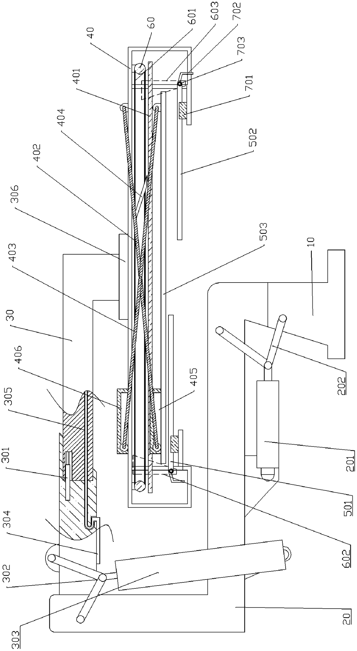
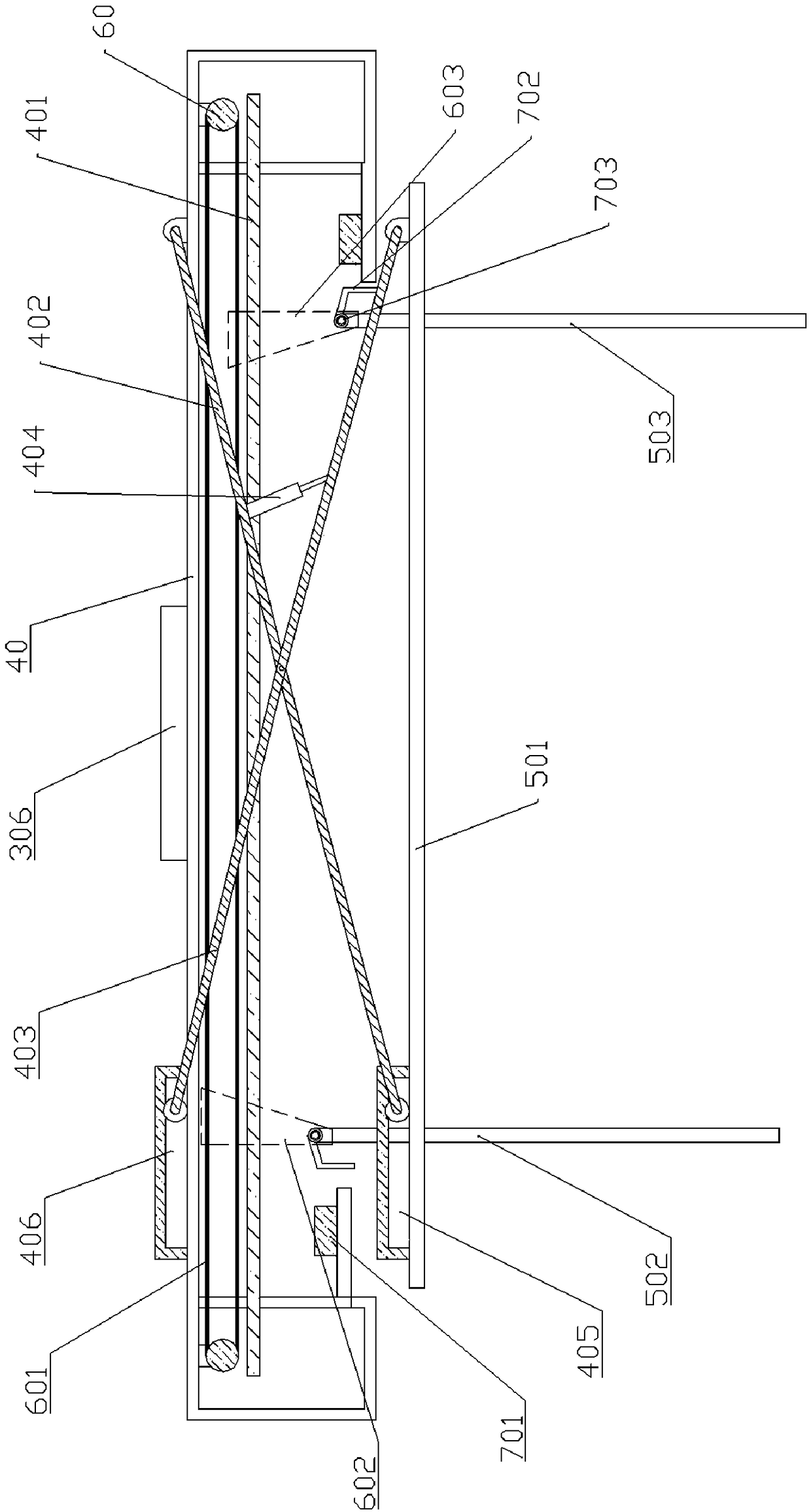
[0022] The reference signs in the drawings of the description include: support base 10, lower arm layer 20, first oil cylinder 201, first hinged rod 202, first rotary motor 203, telescopic arm layer 30, telescopic oil cylinder 301, second hinged rod 302 , the second oil cylinder 303, the water inlet pipe 304, the drag chain 305, the second rotary motor 306, the installation frame layer 40, the slide rail 401, the first connecting rod 402, the second connecting rod 403, the lifting cylinder 404, the first chute 405 , the second chute 406, the first cleaning rod 501, the second cleaning rod 502, the third cleaning rod 503, the sprocket 60, the chain 601, the first slider 602, the second slider 603, the limit block 701, the air Strut 702, spring 703.

[0023] The embodiment is basically as attached figure 1 , attached figure 2 And attached image 3 Shown: a control arm of a decontamination vehi...


PUM


Abstract

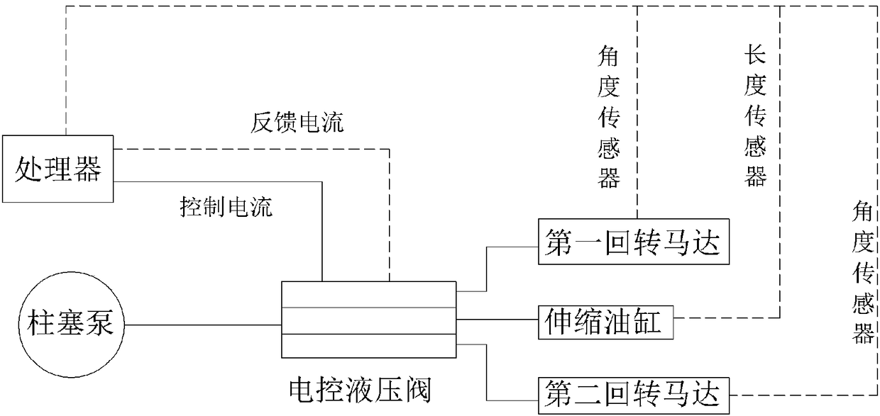
The invention relates to the field of decontamination machines, in particular to a control arm for a decontamination vehicle. The control arm comprises a supporting base, a lower arm layer, a stretchable arm layer, an installing frame layer, a control mechanism and a washing mechanism used for washing equipment; the washing mechanism comprises a transverse beam layer installed on the installing frame layer and a stand column layer, the supporting base, the lower arm layer, the stretchable arm layer and the installing frame layer are sequentially hinged, a first oil cylinder for controlling theangle between the lower arm layer and the supporting base is hinged between the supporting base and the lower arm layer, a first rotation motor is arranged between the supporting base and the lower arm layer, and a second oil cylinder for controlling the angle between the stretchable arm layer and the lower arm layer is arranged between the stretchable arm layer and the lower arm layer; and a second rotation motor is arranged between the stretchable arm layer and the installing frame layer, and the control mechanism is used for controlling the first oil cylinder, the second oil cylinder, thefirst rotation motor and the second rotation motor. By means of the scheme, the positions of the transverse beam layer and the stand column layer are adjusted in real time, and comprehensive and evendecontamination on the equipment can be achieved through the washing mechanism.

Description

technical field [0001] The invention belongs to the field of decontamination machinery, in particular to a control arm of a decontamination vehicle. Background technique [0002] Decontamination refers to measures to disinfect and eliminate contamination of personnel, equipment, materials, fortifications, roads, etc. contaminated with toxic agents, biological warfare agents, and radioactive substances. It is often used in military drills. When personnel, equipment, and the scene are contaminated by chemical agents, biological viruses, and typical toxic and harmful industrial chemicals, equipment with emergency chemical defense spraying and decontamination functions play an important role. Personnel can spray directly, but when encountering equipment with large volume and shape, it is difficult to directly spray the equipment. [0003] At present, in the decontamination process of equipment, vertical spray pipes are often used to spray the surface of the equipment. During th...

Claims


Application Information

Patent Timeline
IPC IPC(8): B08B3/02B08B3/08B08B13/00
Inventor 李国荣廖洋陈尚志谯远朱安娜王志甄周睿周守艳陈嗣钢马宝玉
Owner 重庆军通汽车有限责任公司
Learn More