
A tightening manipulator for a self-returning c-groove precision screw tightening robot

A C-shaped groove and robot technology, applied in metal processing equipment, metal processing, manufacturing tools, etc., can solve the problems of easy slippage and small torque, and achieve the effect of preventing slippage

Active Publication Date: 2020-08-07
江苏二五七特显科技集团有限公司
View PDF7 Cites 1 Cited by
  • Summary
  • Abstract
  • Description
  • Claims
  • Application Information

AI Technical Summary

Problems solved by technology

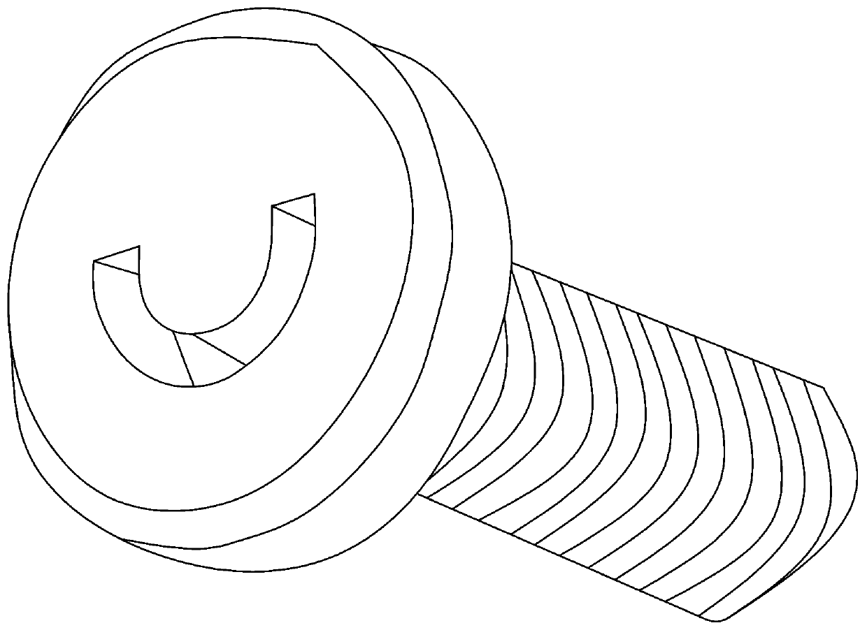
[0002] like figure 1 As shown, there are many kinds of tightening tools on the market for processing non-standard screws with C-shaped grooves, all of which can realize the tightening process of non-standard screws with C-shaped grooves, but in the process of tightening, slipping is prone to occur, and the transmitted small torque

Method used


Image

  • A tightening manipulator for a self-returning c-groove precision screw tightening robot
  • A tightening manipulator for a self-returning c-groove precision screw tightening robot
  • A tightening manipulator for a self-returning c-groove precision screw tightening robot

Examples


Embodiment Construction

[0024] The present invention will be described in further detail below in conjunction with the accompanying drawings and specific embodiments, and the implementation scope of the present invention is not limited thereto.

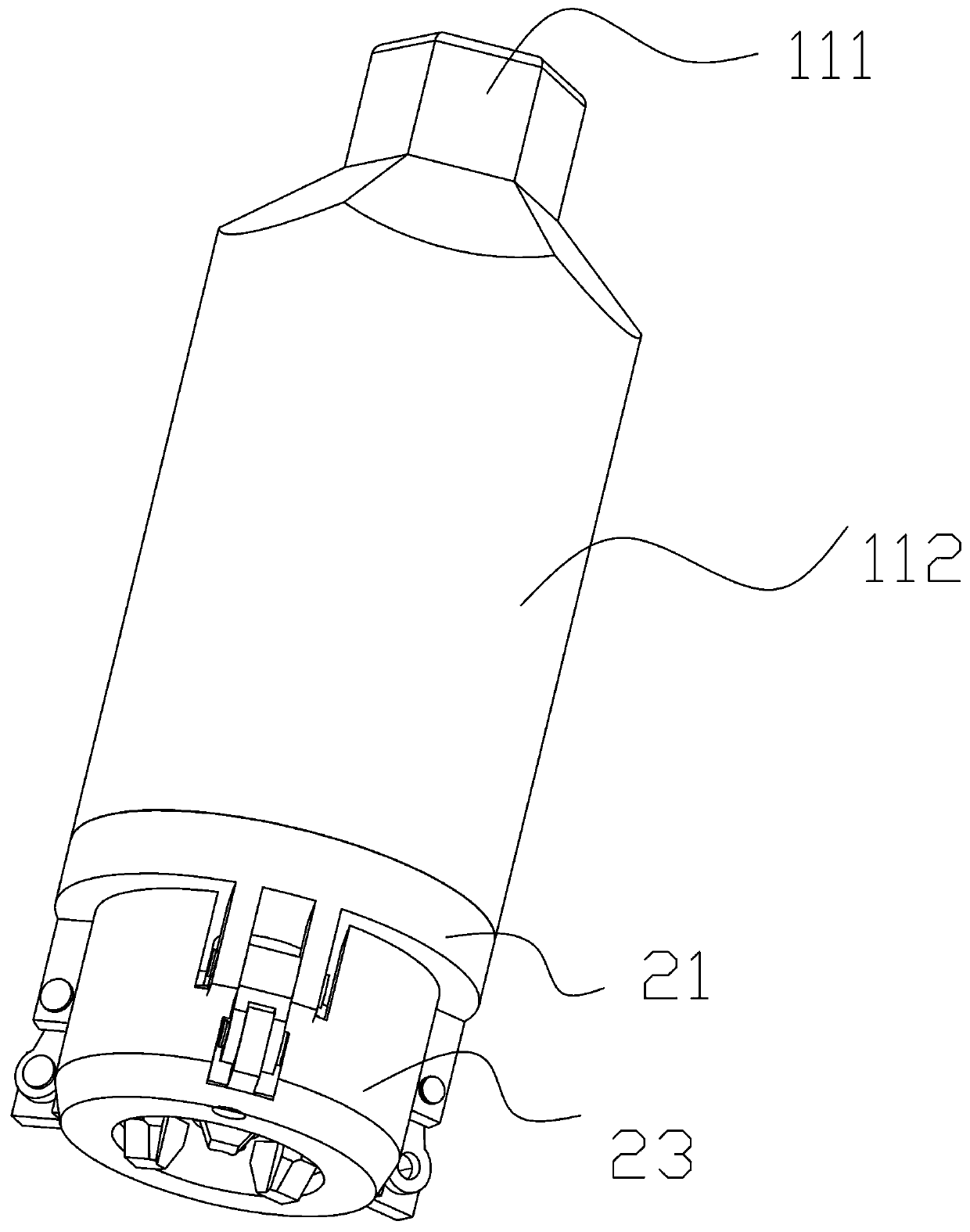
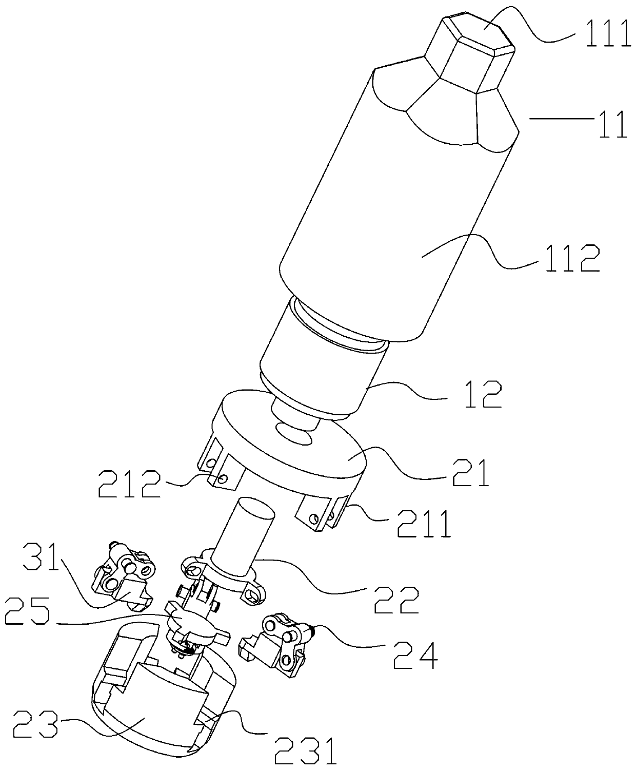
[0025] Such as Figure 2 to Figure 10 As shown, the tightening manipulator for a self-returning C-groove precision screw tightening robot described in this embodiment includes a force supply device and a centrifugal clamping mechanism;

[0026] The power supply device includes a connecting cylinder 11 and an electromagnet 12, the connecting cylinder 11 is used to fix the electromagnet 12, the electromagnet 12 is located in the connecting cylinder 11, and the electromagnet 12 includes a silicon steel frame in the form of an I-shaped wheel, a winding and an iron core, the iron core passes through the inner hole of the silicon steel frame, the winding is used to generate a magnetic field, and the winding is wound on the silicon steel frame, so The iron core is...


PUM


Abstract

The invention relates to a self-deboosting tightening manipulator for a C type groove precise screw tightening robot. A connecting cylinder is used for fixing an electromagnet; one end of a central shaft penetrates through a central hole to be corresponding to an iron core; the interior angle of an L-shaped connecting rod is towards the central shaft; a guiding block is provided with three first sliding chutes, and the opening of each of the first sliding chutes is T-shaped; the first sliding chutes are arranged in the radial direction of the guiding block and communicate with each other; centrifugal blocks are positioned in the first sliding chutes; the upper end of each of the centrifugal blocks is T-shaped; the upper ends of the three centrifugal blocks fit the center to form a triangular first concave pit; the lower surface of each of the three centrifugal blocks is fan-shaped; the lower surfaces of the three centrifugal blocks fit to form a complete circle; an arc-shaped second concave pit is arranged on the outer surface of the lower end of each of the three centrifugal blocks; first springs are arranged in the second concave pits; and a clamping claw is arranged in a secondsliding chute. The self-deboosting tightening manipulator has the characteristics of transmitting larger tightening torque and effectively preventing the slippage phenomenon.

Description

technical field [0001] The invention relates to the technical field of machining screw tightening, in particular to a tightening manipulator for a self-returning force C-groove precision screw tightening robot. Background technique [0002] Such as figure 1 As shown, there are many kinds of tightening tools on the market for processing non-standard screws with C-shaped grooves, all of which can realize the tightening process of non-standard screws with C-shaped grooves, but in the process of tightening, slipping is prone to occur, and the transmitted The torque is small. Contents of the invention [0003] The object of the present invention is to overcome the above-mentioned shortcomings, and provide a C-slot screw tightening chuck that can effectively prevent slippage and transmit relatively large torque. [0004] To achieve the above object, the specific scheme of the present invention is as follows: [0005] A tightening manipulator for a self-returning force C-groov...

Claims


Application Information

Patent Timeline
Patent Type & Authority Patents(China)
IPC IPC(8): B23P19/06
CPCB23P19/06
Inventor 陈云
Owner 江苏二五七特显科技集团有限公司
Learn More