Novel electromagnetic die

An electromagnetic and mold technology, applied in the field of new electromagnetic molds, can solve problems such as failure to meet production requirements, mold top deformation, mold damage, etc., to achieve the effect of ensuring accuracy, avoiding lateral displacement, avoiding deformation and damage to the mold

Inactive Publication Date: 2018-09-21
成都合创智造机械有限公司
View PDF0 Cites 8 Cited by
  • Summary
  • Abstract
  • Description
  • Claims
  • Application Information

AI Technical Summary

Problems solved by technology

When taking out the workpiece, the slider must be in place and the fixed mold should be inserted into the slider at the same time, and there should not be too large a gap that will cause product burrs, which increases the difficulty of the mold and the processing accuracy of each part
At present, most injection mold ejection devices use ejector pins to eject the mold from the mold groove. Because the ejector pin may deform the top of the mold under a certain pressure, or damage the mold, affecting the accuracy of the mold, so that the production requirements cannot be met.

Method used


Image

  • Novel electromagnetic die
  • Novel electromagnetic die

Examples


Embodiment Construction

[0021] The present invention will be further described below in conjunction with accompanying drawing, protection scope of the present invention is not limited to the following:

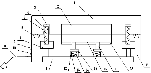
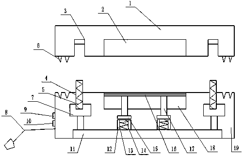
[0022] Such as Figure 1~2 As shown, a novel electromagnetic mold includes an upper mold 1, a lower mold 19, an ejector and a clamping device, and is characterized in that: the upper mold 1 is placed on the upper side of the lower mold 19; the ejector includes Electromagnet 1, magnet I15, push rod 17, switch I9 and support plate 16, described electromagnet I places on the base 11, and described magnet I15 places electromagnet I upper side, and described magnet I15 and push rod 17 bottoms The electromagnet 1 is electrically connected with the switch 19, and the top of the ejector rod 17 is connected with the support plate 16, and the support plate 16 is placed in the lower mold area 18 of the lower mold 19;

[0023] The clamping device includes a magnet II3, an electromagnet II, a support seat 7 and ...


PUM


Abstract

The invention discloses a novel electromagnetic die which comprises an upper die, a lower die, an ejection device and a mode locking device. The upper die is arranged on the upper side of the lower die, the ejection device comprises an electromagnet I, a magnet I, an ejection rod, a switch I and a supporting plate, the mode locking device comprises an electromagnet II, a magnet II, a supporting base and a switch II, the ejection device uses repulsive force generated by the electromagnet I and the magnet I, and the mode locking device uses magnetic force generated by the electromagnet II and the magnet II. The novel electromagnetic die has the beneficial effects that the electromagnetic strong attraction capacity is used, buckling of the upper die and the lower die is achieved, teeth arranged on the upper die and grooves arranged in the lower die are matched, and transverse displacement between the dies is avoided; and through simple mechanical matching, the magnetic force generated bythe electromagnets and the magnets are subject to mutual exclusion, workpieces are ejected out further, deformation and die damage are avoided, the die accuracy is guaranteed, and the production requirement is met.

Description

technical field [0001] The invention relates to the technical field of molds, in particular to a novel electromagnetic mold. Background technique [0002] The mold is a very common device in the machinery industry. The existing mold is generally equipped with a fixed mold and a moving mold that is used in conjunction with the fixed mold. When in use, the fixed mold and the moving mold are matched and then produced After the fixed mold and the movable mold are closed, a force needs to be added to the outside, and the fixed mold and the movable mold are locked by this force to prevent the separation of the fixed mold and the movable mold during use. The existing fixed mold and the movable mold The locking force of the moving mold is mainly provided by the mechanical equipment itself. For example, the injection mold provides the clamping force of the mold through the injection molding machine, and the stamping mold uses the clamping force through the press. However, in the actu...

Claims


Application Information

Patent Timeline
Patent Type & Authority Applications(China)
IPC IPC(8): B29C45/64B29C45/40B29C45/26
CPCB29C45/64B29C45/26B29C45/4005B29C2045/645
Inventor 左强
Owner 成都合创智造机械有限公司
Why Eureka
Try Eureka