
Permanent magnet traction system and rail vehicle

A technology for traction systems and rail vehicles, which is applied in the field of permanent magnet traction systems and rail vehicles, and can solve problems such as motor difficulties and easily damaged inverter devices in traction converters

Pending Publication Date: 2018-09-21
CRRC DALIAN R & D CO LTD
View PDF6 Cites 1 Cited by
  • Summary
  • Abstract
  • Description
  • Claims
  • Application Information

AI Technical Summary

Problems solved by technology

[0004] If the back electromotive force is large when the vehicle is inert, it is easy to damage the inverter device in the traction converter, and it is difficult to put the motor back into operation. Therefore, how to reduce the influence of the back electromotive force when the vehicle is inert is an urgent need for those skilled in the art to solve technical problem

Method used


Image

  • Permanent magnet traction system and rail vehicle
  • Permanent magnet traction system and rail vehicle
  • Permanent magnet traction system and rail vehicle

Examples


Embodiment Construction

[0050] Reference will now be made in detail to the exemplary embodiments, examples of which are illustrated in the accompanying drawings. When the following description refers to the accompanying drawings, the same numerals in different drawings refer to the same or similar elements unless otherwise indicated. The implementations described in the following exemplary examples do not represent all implementations consistent with the present disclosure. Rather, they are merely examples of devices consistent with aspects of the present disclosure as recited in the appended claims.

[0051] The terms "first", "second" and the like in the description and claims of the present invention and the drawings are used to distinguish different objects, rather than to describe a specific order. Furthermore, the terms "include" and "have", as well as any variations thereof, are intended to cover a non-exclusive inclusion. For example, a process, method, system, product or device comprising ...


PUM


Abstract

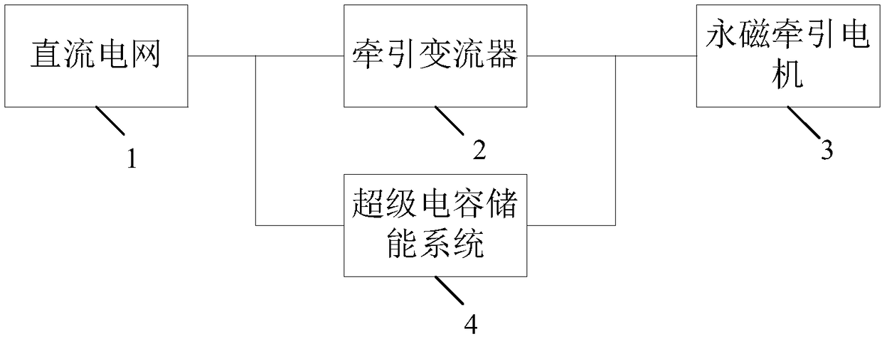
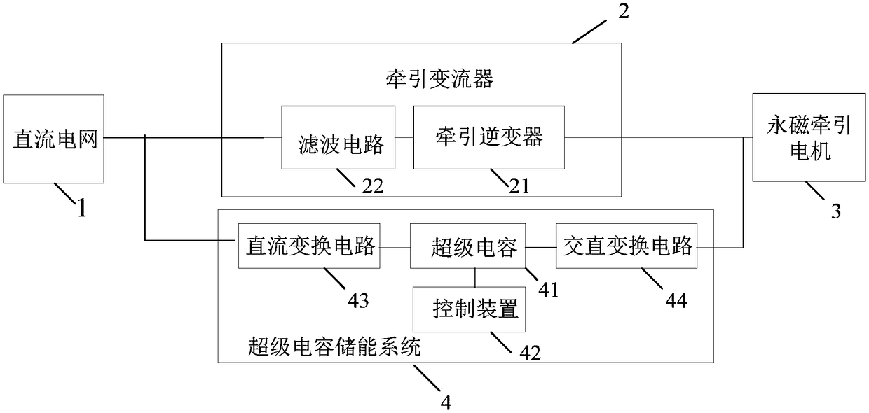
The invention provides a permanent magnet traction system and a rail vehicle. The permanent magnet traction system comprises a direct current power grid, a traction converter, a permanent magnet traction motor and a super-capacitor energy storage system, wherein the direct current power grid, the traction converter and the permanent magnet traction motor are electrically connected with each otherin sequence; the first end of the super-capacitor energy storage system is connected between the direct current power grid and the traction converter; the second end of the super-capacitor energy storage system is connected between the permanent magnet traction motor and the traction converter; and the super-capacitor energy storage system is used for absorbing a counter electromotive force generated by the permanent magnet traction motor during the inertia of the rail vehicle or absorbing braking energy generated by the permanent magnet traction motor during the braking of the rail vehicle. According to the embodiment, the effect of the counter electromotive force, generated by the permanent magnet traction motor, on the traction converter is reduced during the inertia of the rail vehicle; and meanwhile, the energy can be saved.

Description

technical field [0001] The invention relates to the technical field of rail vehicle traction, in particular to a permanent magnet traction system and a rail vehicle. Background technique [0002] With the development of rail transit technology, permanent magnet traction system came into being. The permanent magnet traction system has been widely used due to its advantages of small traction motor and high utilization rate of electric energy. [0003] The permanent magnet traction system consists of two parts: a permanent magnet traction motor and a traction converter. The permanent magnet traction motor has the advantages of high efficiency, high power density, large starting torque and wide speed regulation range. As one of the important parameters of the permanent magnet synchronous motor, the back EMF will affect the performance of the motor and even the entire permanent magnet traction system. [0004] If the back electromotive force is large when the vehicle is inert, ...

Claims


Application Information

Patent Timeline
Patent Type & Authority Applications(China)
IPC IPC(8): B60L9/04B60L11/00
CPCB60L9/04B60L50/40B60L2200/26Y02T10/70
Inventor 张小玲牟岩任宝兵李鹤群韩红彬韩菁候朋岐
Owner CRRC DALIAN R & D CO LTD
Learn More