
Positioning pin mechanism, substrate conveying device and substrate conveying method

A technology of positioning pins and substrates, applied in transportation and packaging, conveyor objects, furnaces, etc., can solve problems such as abnormal quality, easy to scratch the substrate, and complicated movements, and achieve the goal of reducing design costs, avoiding abnormal quality, and reducing costs Effect

Active Publication Date: 2018-09-21
TCL CHINA STAR OPTOELECTRONICS TECH CO LTD
View PDF7 Cites 5 Cited by
  • Summary
  • Abstract
  • Description
  • Claims
  • Application Information

AI Technical Summary

Problems solved by technology

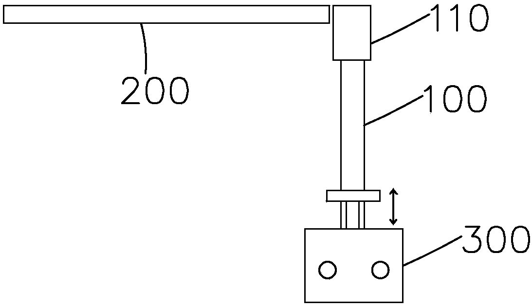
[0005] The first is the "rise and fall" type: the positioning pin can only rise and fall
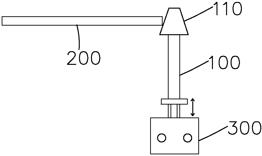
like figure 1 As shown, under this type of movement, the positioning pin 100 can only move up and down driven by the independent cylinder 300. If the positioning contact block 110 is cylindrical, it is very easy to scratch the edge of the substrate (Panel) 200 when falling down, resulting in Shell cracks or fragments and other abnormalities; such as figure 2 As shown, if the positioning contact block 110 of the positioning pin 100 in this type of movement is tapered, the edge of the positioning contact block 110 will wear out with long-term use, and the contact position between the positioning contact block 110 and the substrate 200 will also be worn out. Cylindrical, also causes abnormal quality when dropped
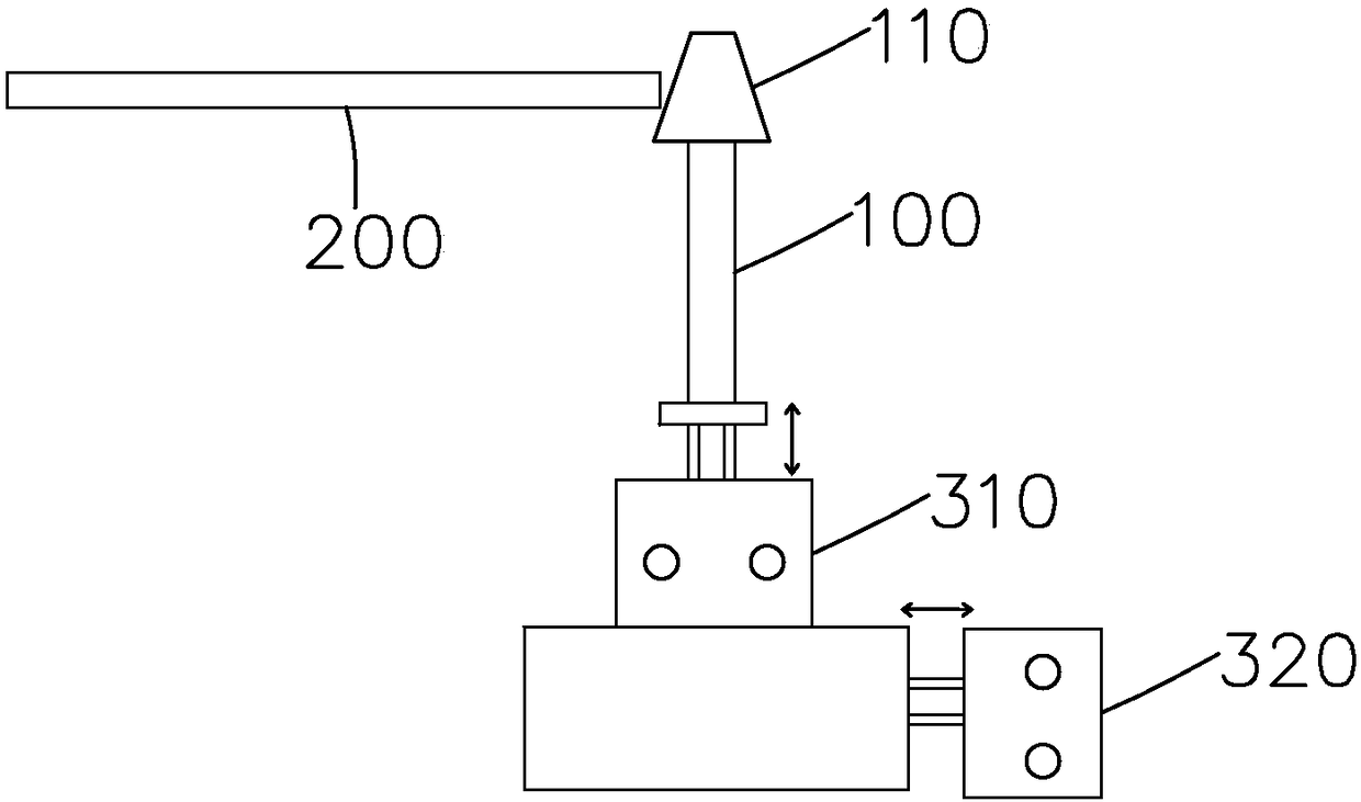
[0006] The second type is the "back and forth, then down" type; the positioning pin can move up and down and left and right, but in this form of movement, two cylinders or coordinated motors are required to act, such as image 3 As shown, the positioning pin 100 can move up and down under the drive of the vertical cylinder 310, and can move left and right under the drive of the horizontal cylinder 320. However, the cost is relatively high, and the movement is complicated, and the frequency of mechanism abnormalities will also double.

Method used


Image

  • Positioning pin mechanism, substrate conveying device and substrate conveying method
  • Positioning pin mechanism, substrate conveying device and substrate conveying method
  • Positioning pin mechanism, substrate conveying device and substrate conveying method

Examples


Embodiment Construction

[0036] In order to further illustrate the technical means adopted by the present invention and its effects, the following describes in detail in conjunction with preferred embodiments of the present invention and accompanying drawings.

[0037] see Figure 4 , the present invention firstly provides a positioning pin mechanism, including a positioning pin 20 and a cylinder 10 that drives the positioning pin 20 to move;

[0038] The cylinder 10 is inclined, including an inclined cylinder 11 and a piston rod 12 telescopically arranged in the cylinder 11, so that the piston rod 12 is inclined with the cylinder 11;

[0039] The positioning pin 20 is bent, including a vertical rod 21 and an inclined rod 22; The lower end is connected to the top of the inclined rod 22, the lower end of the inclined rod 22 is connected to the piston rod 12, and the inclined rod 22 is inclined with the piston rod 12, so that the positioning pin 20 is driven by the cylinder 10 at the same time. Displa...


PUM


Abstract

The invention provides a positioning pin mechanism, a substrate conveying device and a substrate conveying method. The positioning pin mechanism comprises a positioning pin and a cylinder driving thepositioning pin to move; the cylinder comprises an obliquely arranged cylinder body and a piston rod telescopically arranged in the cylinder body, and therefore the positioning pin can be driven by the cylinder to shift in the horizontal direction and the vertical direction at the same time, the design cost can be reduced, and it can be effectively avoided that in the substrate positioning process, because the positioning pin abrades and scratches a substrate, quality abnormity is caused.

Description

technical field [0001] The invention relates to the field of display technology, in particular to a positioning pin mechanism, a substrate transmission device and a substrate transmission method. Background technique [0002] Glass substrates are basic components of various display devices. For example, the use of glass substrates is indispensable in various display panels, and various processes need to be performed on the display panels during the manufacturing process of the display panels. In the automatic production line, the transmission error in the transmission process of the glass substrate is relatively large, especially the cumulative error generated in the fast transmission or long-distance transmission is particularly prominent. Therefore, an important process step in the display panel manufacturing process is, in the On the production line, the glass substrates need to be corrected to a certain position one by one (for example, positioned on a centerline), so as...

Claims


Application Information

Patent Timeline
Patent Type & Authority Applications(China)
IPC IPC(8): B65G49/06
CPCB65G49/063
Inventor 刘猛猛
Owner TCL CHINA STAR OPTOELECTRONICS TECH CO LTD
Learn More