
Eureka
For R&D, Eureka makes reading and utilizing patents & technical documents easy.
Eureka AIR
Designed for self-driven R&D workflows. Generate viable solutions, solve complex R&D challenges, empower your innovation with AI.

Eureka Materials
Designed for material experts only. Revolutionize your material R&D, from search, analyze, to developing new materials.

TechResearch
Generate reliable direction feasibility study reports for your R&D in just a few steps.

TechSeek
Discover and master advanced knowledge NOW. Basics, ideas, possibilities, all at once.

TechMind
As an expert in R&D Theories, TechMind can generates customized viable solutions instantly.

TechRisk
Analyze your overall solution with one click, know your potential R&D risks in advance.

TechMonitor
Get weekly tech updates, stay abreast of the latest tech innovations and key insights.
Concrete pavement expansion joint filling equipment
A technology for cement pavement and expansion joints, which can be used in roads, roads, road repair and other directions, and can solve the problems of uneven filling and high labor intensity.
- Summary
- Abstract
- Description
- Claims
- Application Information
AI Technical Summary
Problems solved by technology
Method used
Image

Examples
Embodiment 1
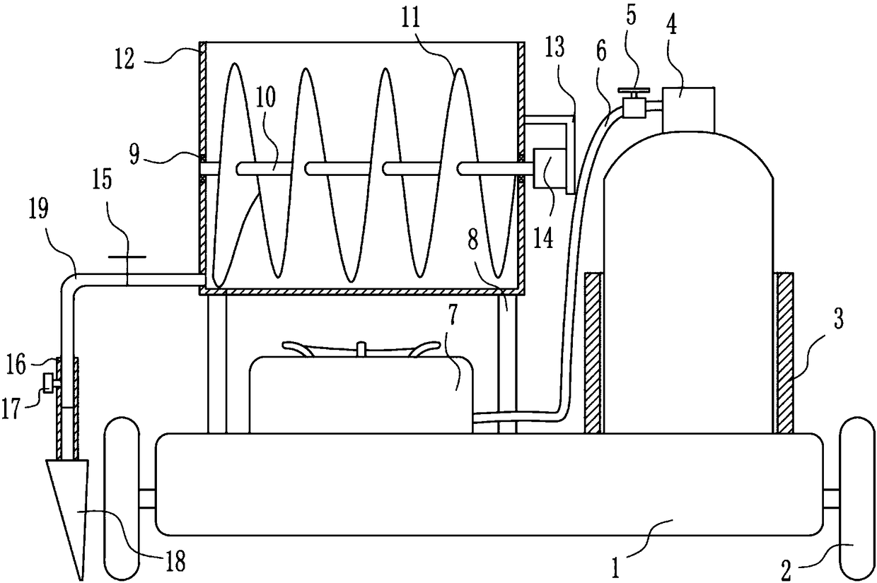
[0020] A cement pavement expansion joint joint filling equipment, such as Figure 1-3 As shown, it includes base plate 1, wheel 2, placement frame 3, gas tank 4, first valve 5, gas outlet pipe 6, gas stove 7, support rod 8, first bearing seat 9, first rotating rod 10, helical blade 11. Frame body 12, 7-type plate 13, motor 14, second valve 15, hollow pipe 16, fastening bolt 17, lower hopper 18 and discharge pipe 19, wheels 2 are installed on the lower parts of the left and right sides of the bottom plate 1, the bottom plate 1. A placement frame 3 is installed on the right side of the top, and a gas tank 4 is arranged in the placement frame 3. The gas outlet end of the gas tank 4 is connected with a gas outlet pipe 6. The gas outlet pipe 6 is provided with a first valve 5. Both support rods 8 are installed, and a frame body 12 is installed between the tops of the support rods 8 on the left and right sides. The middle part of the left side of the frame body 12 and the middle par...
Embodiment 2
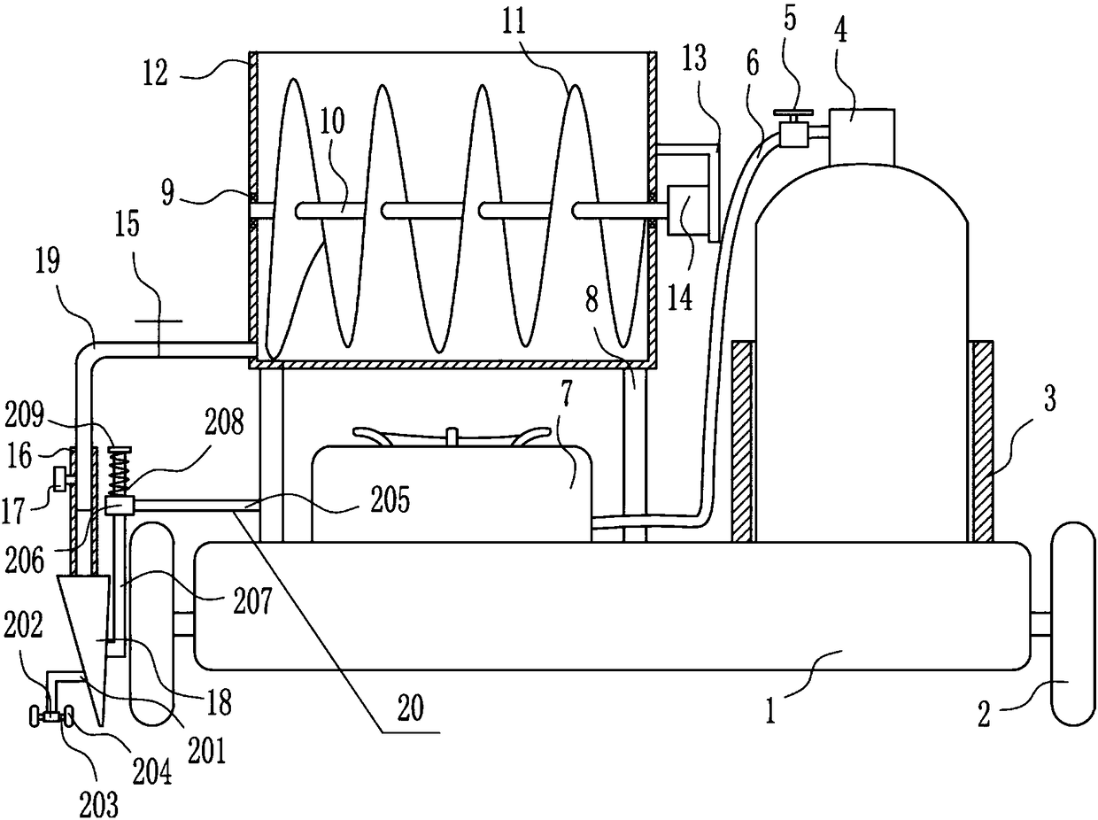
[0022] A cement pavement expansion joint joint filling equipment, such as Figure 1-3As shown, it includes base plate 1, wheel 2, placement frame 3, gas tank 4, first valve 5, gas outlet pipe 6, gas stove 7, support rod 8, first bearing seat 9, first rotating rod 10, helical blade 11. Frame body 12, 7-type plate 13, motor 14, second valve 15, hollow pipe 16, fastening bolt 17, lower hopper 18 and discharge pipe 19, wheels 2 are installed on the lower parts of the left and right sides of the bottom plate 1, the bottom plate 1. A placement frame 3 is installed on the right side of the top, and a gas tank 4 is arranged in the placement frame 3. The gas outlet end of the gas tank 4 is connected with a gas outlet pipe 6. The gas outlet pipe 6 is provided with a first valve 5. Both support rods 8 are installed, and a frame body 12 is installed between the tops of the support rods 8 on the left and right sides. The middle part of the left side of the frame body 12 and the middle part...
Embodiment 3
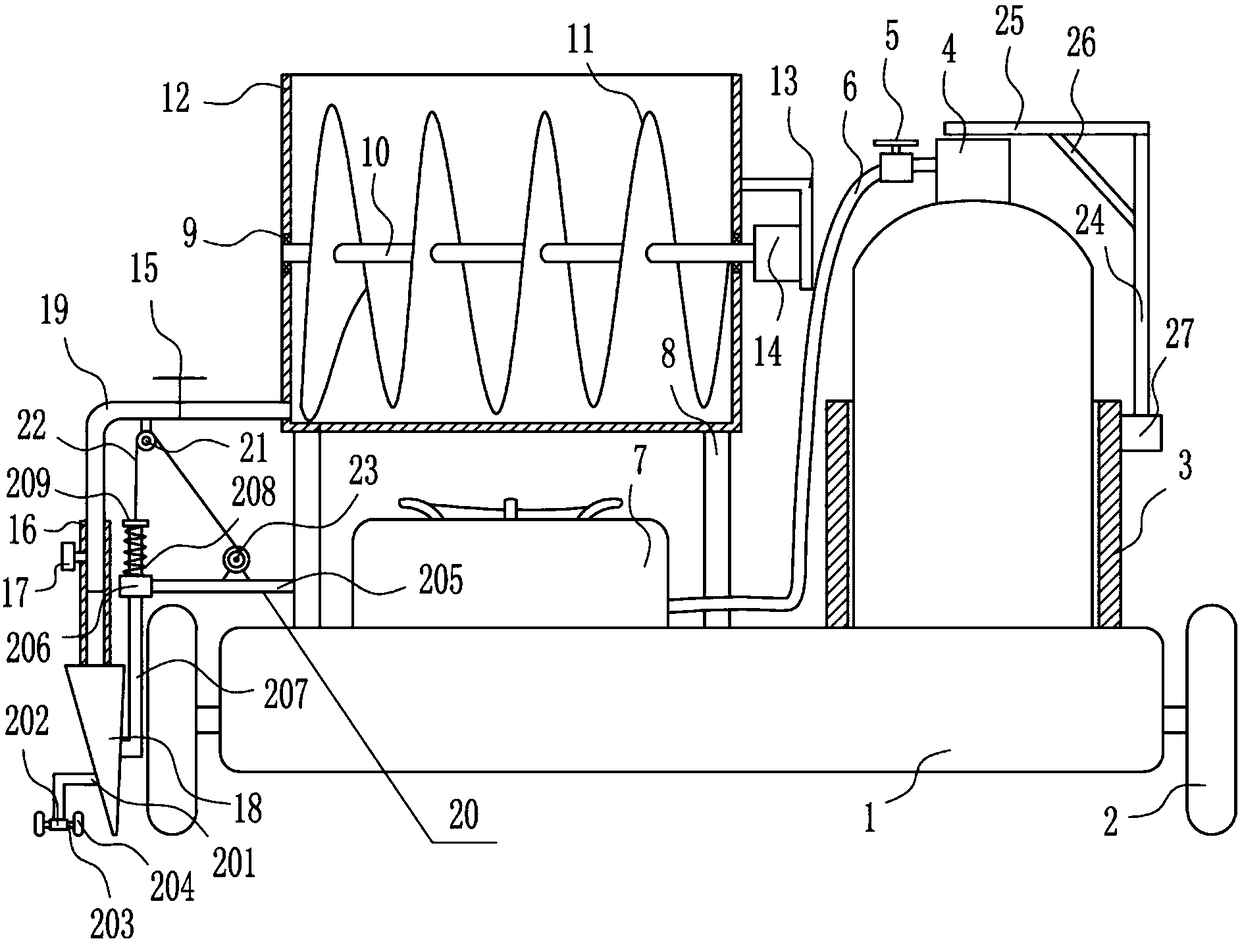
[0025] A cement pavement expansion joint joint filling equipment, such as Figure 1-3 As shown, it includes base plate 1, wheel 2, placement frame 3, gas tank 4, first valve 5, gas outlet pipe 6, gas stove 7, support rod 8, first bearing seat 9, first rotating rod 10, helical blade 11. Frame body 12, 7-type plate 13, motor 14, second valve 15, hollow pipe 16, fastening bolt 17, lower hopper 18 and discharge pipe 19, wheels 2 are installed on the lower parts of the left and right sides of the bottom plate 1, the bottom plate 1. A placement frame 3 is installed on the right side of the top, and a gas tank 4 is arranged in the placement frame 3. The gas outlet end of the gas tank 4 is connected with a gas outlet pipe 6. The gas outlet pipe 6 is provided with a first valve 5. Both support rods 8 are installed, and a frame body 12 is installed between the tops of the support rods 8 on the left and right sides. The middle part of the left side of the frame body 12 and the middle par...
PUM
 Abstract
Description
Claims
Application Information
 - R&D Engineer
- R&D Manager
- IP Professional
- Industry Leading Data Capabilities
- Powerful AI technology
- Patent DNA Extraction
Browse by: Latest US Patents, China's latest patents, Technical Efficacy Thesaurus, Application Domain, Technology Topic, Popular Technical Reports.
© 2024 PatSnap. All rights reserved.Legal|Privacy policy|Modern Slavery Act Transparency Statement|Sitemap|About US| Contact US: help@patsnap.com