Ring rib pin tenon connection structure of concrete member and construction method thereof

A technology for connecting structures and concrete, applied in the direction of building structure, construction, etc., can solve the problems of raising the overall cost of concrete prefabricated components, unfavorable promotion and popularization of prefabricated buildings, and high bolt connection costs, and achieves convenient detection and application scope. Wide and convenient construction

Pending Publication Date: 2018-09-21
SHANGHAI CITI RAISE CONSTR GRP
View PDF5 Cites 2 Cited by
  • Summary
  • Abstract
  • Description
  • Claims
  • Application Information

AI Technical Summary

Problems solved by technology

Since the density and strength of the grout in the sleeve or in the round hole cannot be tested non-destructively on site, this connection method has caused considerable controversy in the industry, and has even been questioned by structural engineers. The cost of the method is high, which increases the overall cost of prefabricated concrete components, which is not conducive to the promotion and popularization of prefabricated buildings; and the bolt connection in the mechanical connection is also difficult to popularize because of the high cost; and other methods in the mechanical connection , and welded connections, lashing connections, etc. are mainly used for cast-in-place parts of concrete components

Method used


Image

  • Ring rib pin tenon connection structure of concrete member and construction method thereof
  • Ring rib pin tenon connection structure of concrete member and construction method thereof
  • Ring rib pin tenon connection structure of concrete member and construction method thereof

Examples


Embodiment 1

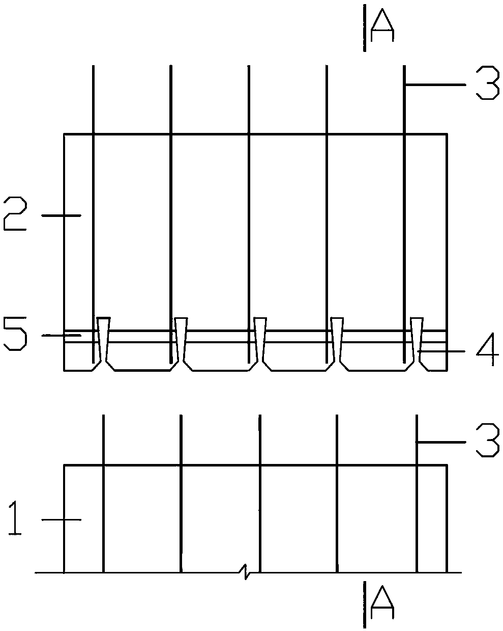
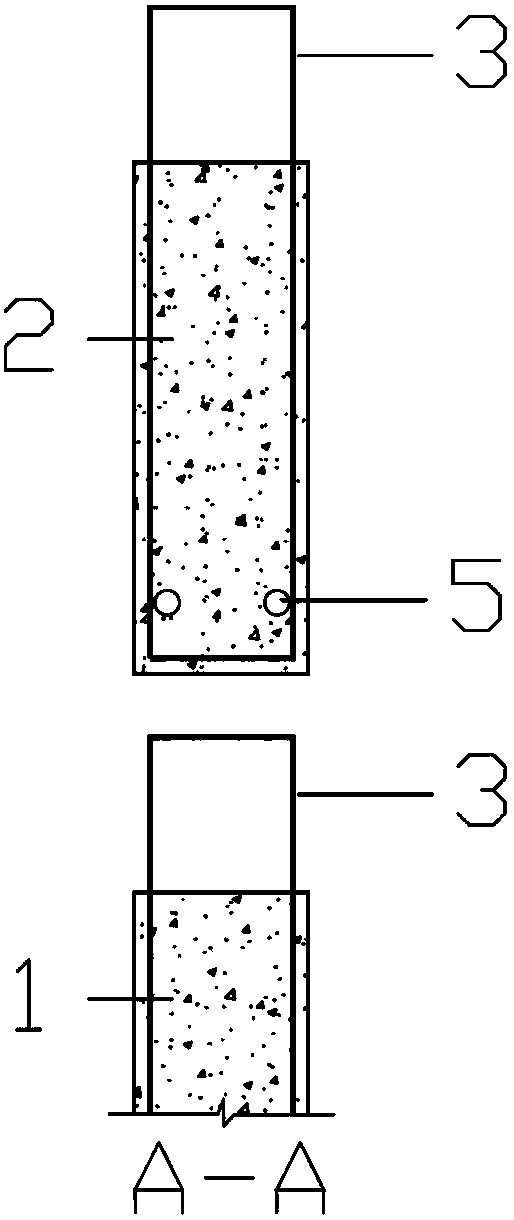
[0070] The first step: processing pre-embedded ring reinforcement 3;

[0071] The second step: constructing the concrete member 1 including the pre-embedded ring reinforcement 3;

[0072] The third step: constructing the concrete member 2 including the reserved tenon and groove 4 and the reserved pin hole 5;

[0073] Part 4: Lift the concrete member 2 containing the reserved tenon groove 4 and the reserved pin hole 5 to the position of the concrete member 1 containing the pre-embedded ring reinforcement 3, move and insert the pre-embedded ring reinforcement 3 into the reserved tenon groove 4 ;

[0074] Step 5: Insert the pin 6 into the reserved pin hole 5;

[0075] Step 6: Clamp and seal the periphery of the concrete member 2 including the reserved mortise 4 and the reserved pin hole 5 with a splint, and pour the glue into the reserved mortise 4 and the reserved pin hole 5 The grout is formed to form the joint grout 7.

Embodiment 2

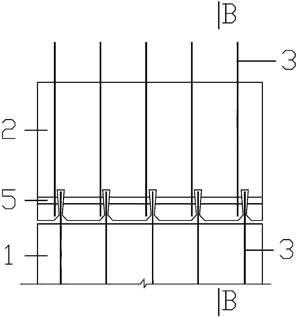
[0077] The first step: processing pre-embedded ring reinforcement 3;

[0078] The second step: constructing the concrete member 1 including the concrete tenon 8 and the embedded ring reinforcement 3;

[0079] The third step: constructing the concrete member 2 including the reserved tenon and groove 4 and the reserved pin hole 5;

[0080] Part 4: Lift the concrete member 2 containing the reserved tenon groove 4 and the reserved pin hole 5 to the position of the concrete member 1 containing the concrete tenon 8 and the embedded ring reinforcement 3, move and insert the concrete tenon 8 into the reserved Tenon and groove 4;

[0081] Step 5: Insert the pin 6 into the reserved pin hole 5;

[0082] Step 6: Clamp and seal the periphery of the concrete member 2 including the reserved mortise 4 and the reserved pin hole 5 with a splint, and pour the glue into the reserved mortise 4 and the reserved pin hole 5 The grout is formed to form the joint grout 7.

[0083] The ring reinforc...


PUM


Abstract

The invention relates to a ring rib pin tenon connection structure of concrete members with pin bolt connection used in combination with tenon connection. The ring rib pin tenon connection structure of the concrete members is characterized in that the ring rib pin tenon connection structure consists of pre-embedded ring ribs, reserved tenon grooves, reserved pin holes, pins and grouting slurry ofthe concrete members; connection ends of two concrete members connected to each other are provided, wherein one ends are the pre-embedded ring ribs, and the others are the reserved tenon grooves and pin holes; the pre-embedded ring ribs of one member or tenons pre-embedded with ring ribs are inserted into the tenon grooves of another member; the pins are then inserted into the reserved pin holes;bonding slurry is filled or injected into the gaps inside the tenon grooves and pin holes of the members; after the slurry solidifies, the slurry becomes grouting slurry, and the two concrete membersare connected together. A construction method of the ring rib pin tenon connection structure is also related to. The ring rib pin tenon connection structure and the construction method thereof have the advantages of not only reducing costs but also improving safety of the structure, facilitating construction and inspection, and having broad application prospects.

Description

technical field [0001] The invention relates to the technical field of concrete structures in civil engineering, in particular to a connection structure of concrete components, in particular to a ring reinforcement pin tenon connection structure of concrete components and a construction method thereof. Background technique [0002] At present, the gradual replacement of cast-in-place concrete structures by prefabricated concrete structures is an inevitable trend in the development of the construction industry, and has even become a national development strategy. The connection technology of prefabricated concrete components in the construction of prefabricated concrete structures is usually in the form of sleeve grouting connection, grout anchor lap connection, mechanical connection, welding connection and lashing lap connection. Among them, the first two are the main connection forms of vertical prefabricated components. The connection principles of the two are similar. The...

Claims


Application Information

Patent Timeline
Patent Type & Authority Applications(China)
IPC IPC(8): E04B1/38
CPCE04B1/38E04B1/383
Inventor 王立明
Owner SHANGHAI CITI RAISE CONSTR GRP
Why Eureka
Try Eureka