Stereoscopic parking equipment

A three-dimensional parking and equipment technology, which is applied in the direction of buildings, building types, buildings, etc. where cars are parked, can solve the problems of high cost of parking space expansion, large land occupation, lack of physical space, etc., and achieve novel parking methods and ingenious structural design , reasonable effect of space utilization

Pending Publication Date: 2018-09-21
SHENZHEN POLYTECHNIC
View PDF0 Cites 0 Cited by
  • Summary
  • Abstract
  • Description
  • Claims
  • Application Information

AI Technical Summary

Problems solved by technology

Even so, the parking spaces are not enough. At the same time, the expansion cost of the parking spaces is high, and it also needs to occupy a lot of land resources, and many communities themselves lack more physical space, and the impact on greening and community housing needs to be considered
[0003] Aiming at the existing parking problems, a three-dimensional parking equipment is now provided, which is designed based on the current situation of most communities, realizes the utilization of three-dimensional space, realizes parking on the three-dimensional space, and achieves without affecting the greening and living experience of the community Under the circumstances, the space utilization rate will be improved to solve the current problem of insufficient parking spaces

Method used


Image

  • Stereoscopic parking equipment
  • Stereoscopic parking equipment
  • Stereoscopic parking equipment

Examples


Embodiment 1

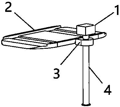
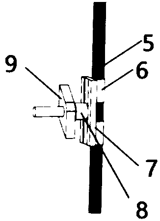
[0028] see Figure 1-7 , a three-dimensional parking equipment, comprising a driving device 1, a rail sleeve 4, a vehicle-mounted board 2 and a screw transmission device 3 fixed on the side wall of the vehicle-mounted board 2, and the screw transmission device 3 includes a vertically arranged drive device 1 The screw rod 5 connected by drive, the screw rod 5 vertically penetrates the inside of the rail sleeve 4, the surface of the screw rod 5 is threadedly connected and sleeved with a nut 6, the side wall of the nut 6 is fixedly installed with a connecting plate 7, and the side wall of the connecting plate 7 is horizontal A connecting rod 8 is fixedly installed, and the surface of the connecting rod 8 is rotatably provided with a collision block 9. The rail sleeve 4 is provided with a slide rail 16 that runs through its side wall, and the collision block 9 is slidably embedded in the slide rail 16. , the slide rail 16 includes an upper straight rail 161, a ramp 162 and a lower...

Embodiment 2

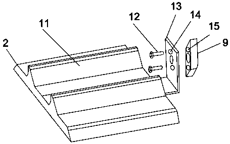
[0056] On the basis of Embodiment 1, in addition, several inclined baffles 11 are fixedly installed on the upper surface of the vehicle-mounted board 2, and by the inclined baffles 11 provided, when the vehicle-mounted board 2 is tilted when it rises or falls, the inclination The baffle plate 11 can play a position-limiting role, preventing the car from slipping off the vehicle-mounted board 2, and ensuring the stability of the car's lifting process.

Embodiment 3

[0058] On the basis of Embodiment 2, in addition, the side wall of the collision block 9 is provided with a threaded hole 15, and the connecting block 13 is provided with a mounting hole 14 corresponding to the horizontal direction of the threaded hole 15, and the mounting hole 14 is threaded with the threaded hole 15. 12 screws for connection. The connection between the screw 12 and the threaded hole 15 ensures that the bumper 9 is deflected to drive the vehicle board 2 to rotate smoothly, which improves the stability of the vehicle on the vehicle board 2 .

[0059] In summary, the rail sleeve 4, the vehicle-mounted board 2, and the driving device 1 in this device are direct applications of prior art means; the slide rail 16, the bumper 9 and the vehicle-mounted board 2 The baffle plate 11 on the top is the invention point of this technical solution. The parking method of this equipment makes the vehicle obliquely avoid the obstacles of the ground vehicle, shortens the time a...


PUM


Abstract

The invention discloses stereoscopic parking equipment which comprises a driving device, a tracked sleeve, a vehicle-mounted plate and a spiral transmission device fixed to a lateral wall of the vehicle-mounted plate, wherein the spiral transmission device comprises a screw rod, the screw rod is vertically arranged and is in driving connection with the driving device, and the screw rod verticallypenetrates through the inside of the tracked sleeve; a sliding rail comprises an upper straight rail, an inclined rail and a lower straight rail which are in smooth transition from top to bottom, andthe inclined rail extends along a lateral wall of the curve surface of the tracked sleeve; a connection block is fixedly arranged on a lateral wall of a striking block, and the vehicle-mounted plate is fixedly arranged on the connection block. The stereoscopic parking equipment disclosed by the invention has the beneficial effects: 1, the parking mode is novel: a vehicle obliquely avoids ground vehicle obstacles, vehicle operation time and space are shortened, and occupation space of the whole parking lot is saved; 2, space is reasonably utilized: upper-layer space of existing ground parking spots is perpendicularly utilized, and no other land source is occupied; 3, the space utilization rate is doubled: a certain spatial angle is formed between an upper-layer parking spot and a ground parking spot, and the parking spots are twice of the ground.

Description

technical field [0001] The invention relates to the technical field of parking equipment, in particular to a three-dimensional parking equipment. Background technique [0002] With the continuous popularization of automobiles, the number of automobiles is constantly increasing every year, and many communities have experienced the embarrassment of insufficient parking spaces. Many communities planned two-way streets in the early days, but now they have to use one road for parking. Even so, the parking spaces are not enough. At the same time, the expansion cost of the parking spaces is high, and it also needs to occupy a lot of land resources, and many communities themselves lack more physical space, and the impact on greening and community housing needs to be considered. [0003] Aiming at the existing parking problems, a three-dimensional parking equipment is now provided, which is designed based on the current situation of most communities, realizes the utilization of thre...

Claims


Application Information

Patent Timeline
Patent Type & Authority Applications(China)
IPC IPC(8): E04H6/02E04H6/04E04H6/06
CPCE04H6/025E04H6/04E04H6/065
Inventor 赖权康张学璇田荣锋
Owner SHENZHEN POLYTECHNIC
Why Eureka
Try Eureka