
Detection device for pipe fitting hole distance

A detection device and hole spacing technology, which is applied in the direction of measuring device, mechanical device, mechanical measuring device, etc., can solve the problems of inability to meet the detection requirements of different pipe fittings, inability to adjust, and prone to errors, etc., to achieve easy maintenance and repair. , The effect of low manufacturing and maintenance costs, and the effect of reducing the burden

Inactive Publication Date: 2018-09-21
蒋孔焕
View PDF0 Cites 6 Cited by
  • Summary
  • Abstract
  • Description
  • Claims
  • Application Information

AI Technical Summary

Problems solved by technology

[0004] In order to overcome the fact that the existing detection devices are hand-held by the staff to detect the pipe fittings, it is time-consuming and labor-intensive, and errors are prone to occur. At the same time, the existing detection devices usually use traditional fixed structures, which cannot be adjusted, and can only be adjusted for the hole distance of a single pipe fitting. Detection cannot meet the detection requirements for different pipe hole distances, and requires enterprises to purchase detection devices of various specifications. Therefore, the technical problem of the present invention is: to provide a time-saving, labor-saving, flexible structure, and easy to adjust for pipe fittings. Hole distance detection device

Method used


Image

  • Detection device for pipe fitting hole distance
  • Detection device for pipe fitting hole distance
  • Detection device for pipe fitting hole distance

Examples


Embodiment 1

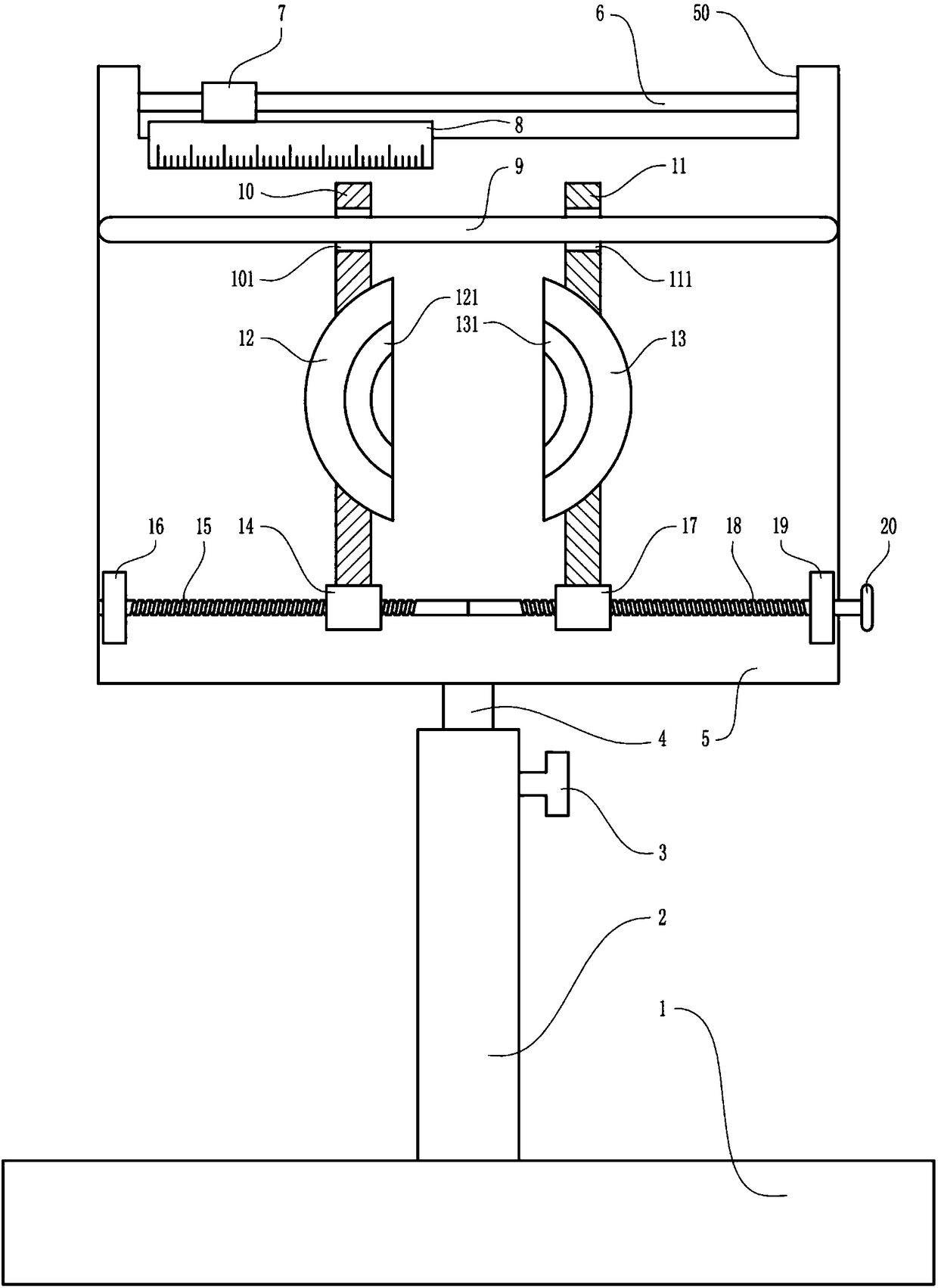
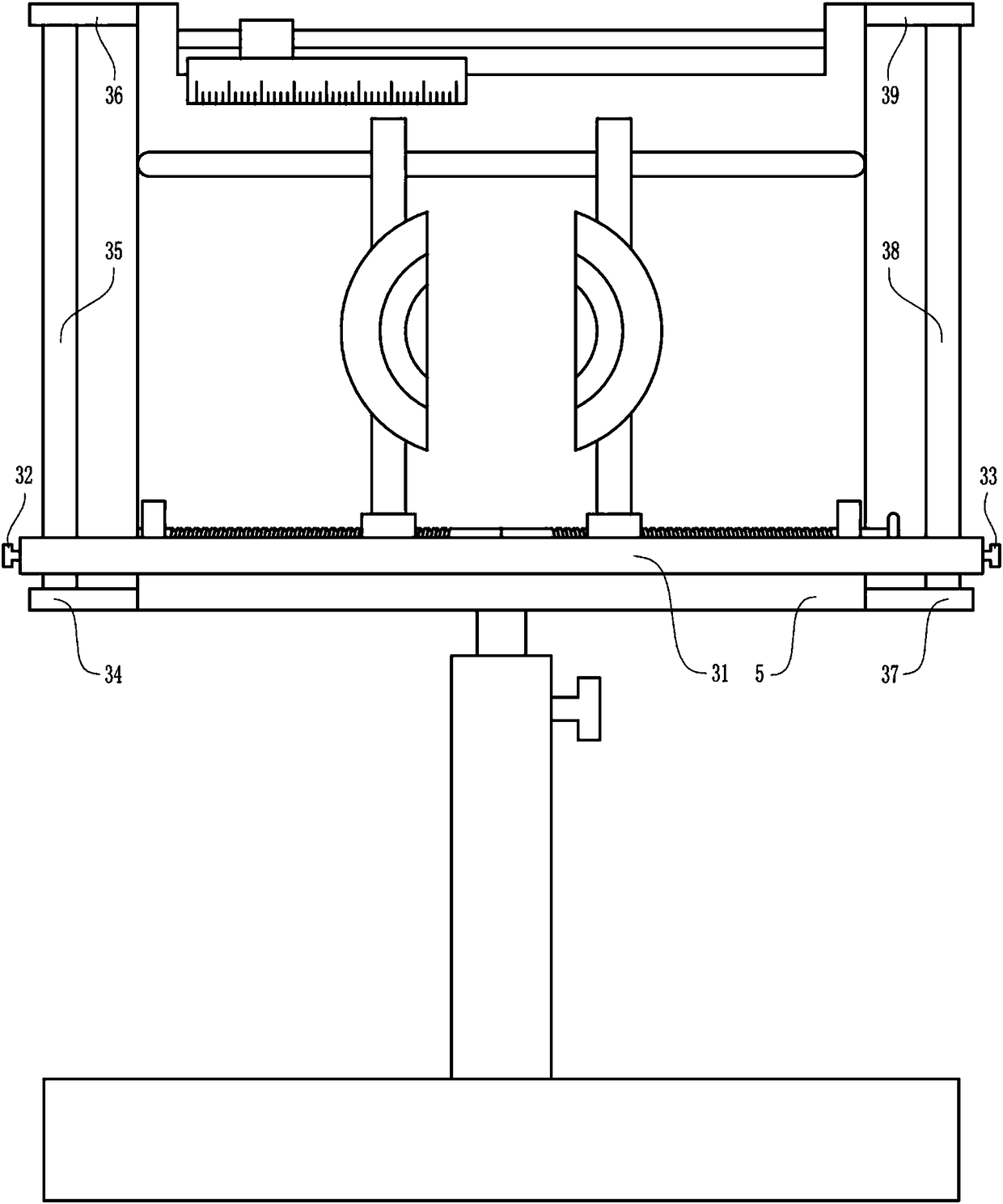
[0023] A detection device for the hole distance of pipe fittings, such as Figure 1-6As shown, it includes base 1, large casing 2, large positioning screw 3, lifting rod 4, large fixed plate 5, long guide rod 6, guide sleeve 7, scale 8, U-shaped guide rod 9, first guide plate 10. The second guide plate 11, the first arc block 12, the second arc block 13, the first nut 14, the first screw 15, the first bearing seat 16, the second nut 17, the second screw 18, The second bearing seat 19 and the rotating wheel 20, the large casing 2 is located above the base 1, the bottom of the large casing 2 is connected with the middle position of the top of the base 1, and the upper threaded connection of the right side wall of the large casing 2 has a large positioning The screw 3 and the lifting rod 4 are slidingly located in the large casing 2, the large positioning screw 3 is in contact with the lifting rod 4, the upper end of the lifting rod 4 is connected with a large fixing plate 5, and...

Embodiment 2

[0025] A detection device for the hole distance of pipe fittings, such as Figure 1-6 As shown, it includes base 1, large casing 2, large positioning screw 3, lifting rod 4, large fixed plate 5, long guide rod 6, guide sleeve 7, scale 8, U-shaped guide rod 9, first guide plate 10. The second guide plate 11, the first arc block 12, the second arc block 13, the first nut 14, the first screw 15, the first bearing seat 16, the second nut 17, the second screw 18, The second bearing seat 19 and the rotating wheel 20, the large casing 2 is located above the base 1, the bottom of the large casing 2 is connected with the middle position of the top of the base 1, and the upper threaded connection of the right side wall of the large casing 2 has a large positioning The screw 3 and the lifting rod 4 are slidingly located in the large casing 2, the large positioning screw 3 is in contact with the lifting rod 4, the upper end of the lifting rod 4 is connected with a large fixing plate 5, an...

Embodiment 3

[0028] A detection device for the hole distance of pipe fittings, such as Figure 1-6 As shown, it includes base 1, large casing 2, large positioning screw 3, lifting rod 4, large fixed plate 5, long guide rod 6, guide sleeve 7, scale 8, U-shaped guide rod 9, first guide plate 10. The second guide plate 11, the first arc block 12, the second arc block 13, the first nut 14, the first screw 15, the first bearing seat 16, the second nut 17, the second screw 18, The second bearing seat 19 and the rotating wheel 20, the large casing 2 is located above the base 1, the bottom of the large casing 2 is connected with the middle position of the top of the base 1, and the upper threaded connection of the right side wall of the large casing 2 has a large positioning The screw 3 and the lifting rod 4 are slidingly located in the large casing 2, the large positioning screw 3 is in contact with the lifting rod 4, the upper end of the lifting rod 4 is connected with a large fixing plate 5, an...


PUM


Abstract

The invention relates to a detection device for a pipe fitting, in particular to a detection device for pipe fitting hole distance. Therefore, the to-be-solved technical problem is to provide a detection device for pipe fitting hole distance with the advantages that the time and labor are reduced, the structure is flexible, and the adjustment is convenient. According to the technical scheme, the detection device for the pipe fitting hole distance comprises a base, a big casing, a big positioning threaded rod, a lifting rod, a big fixing plate, a long guide rod, a guide sleeve, a calibrated scale, a U-shaped guide rod, a first guide plate and the like; the big casing is arranged on the upper portion of the base, the bottom of the big casing is connected with the middle portion of the top ofthe base, the upper portion of the right side wall of the big casing is in threaded connection with the big positioning threaded rod, and the lifting rod is slidably located in the big casing. The provided detection device for the pipe fitting hole distance has the advantages that a worker does not need to hold the device, the structure is flexible, the device can be adjusted conveniently, the pipe fitting hole distance with different specifications can be detected, the detection efficiency is high, the time and labor are reduced, the detection precision is high, and the cost expenditure of enterprises is reduced.

Description

technical field [0001] The invention relates to a detection device for pipe fittings, in particular to a detection device for the hole distance of pipe fittings. Background technique [0002] After the pipe fittings are made, they need to be inspected. The inspection of the hole distance of the pipe fittings is an important inspection to judge whether the pipe fittings are qualified. It is an important checkpoint to ensure the quality of the pipe fittings and a powerful guarantee for the life of the enterprise. It is time-consuming and labor-intensive to detect pipe fittings with a hand-held detection device, and errors are prone to occur. At the same time, the existing detection devices usually use traditional fixed structures, which cannot be adjusted. In order to meet the testing requirements, enterprises need to purchase testing devices of various specifications, which increases the cost of enterprises. [0003] Therefore, there is an urgent need to develop a time-savin...

Claims


Application Information

Patent Timeline
Patent Type & Authority Applications(China)
IPC IPC(8): G01B5/14
CPCG01B5/143G01B5/0002
Inventor 蒋孔焕
Owner 蒋孔焕
Learn More