
Oil well wellhead water content automatic test device and test method thereof

An automatic testing device and automatic testing technology, applied in the direction of measuring devices, instruments, scientific instruments, etc., can solve the problem of increasing the workload and intensity of staff sampling, sending samples and monitoring water cut, failing to grasp the production of oil wells in a timely and accurate manner, and lagging monitoring results and other issues, to achieve the effect of perfecting the level of digital management, reducing labor, and avoiding lag

Pending Publication Date: 2018-09-21
PETROCHINA CO LTD
View PDF9 Cites 2 Cited by
  • Summary
  • Abstract
  • Description
  • Claims
  • Application Information

AI Technical Summary

Problems solved by technology

Usually in various oil fields, the measurement of oil well water content needs to be obtained through the process of oil well head sampling, sample transportation and central laboratory testing. The monitoring results are often lagging behind, and the oil well production cannot be grasped in a timely and accurate manner.
At the same time, due to the large number of oil wells in each oil field and the scattered blocks, with the current monitoring methods, it is necessary to build a larger number of testing centers and invest more manpower, and it also greatly increases the number of staff sampling, sending samples and monitoring water content. The workload and intensity caused great difficulties to the normal production management on site

Method used


Image

  • Oil well wellhead water content automatic test device and test method thereof
  • Oil well wellhead water content automatic test device and test method thereof

Examples


Embodiment Construction

[0031] The present invention will be further described in detail below in conjunction with specific embodiments, which are explanations of the present invention rather than limitations.

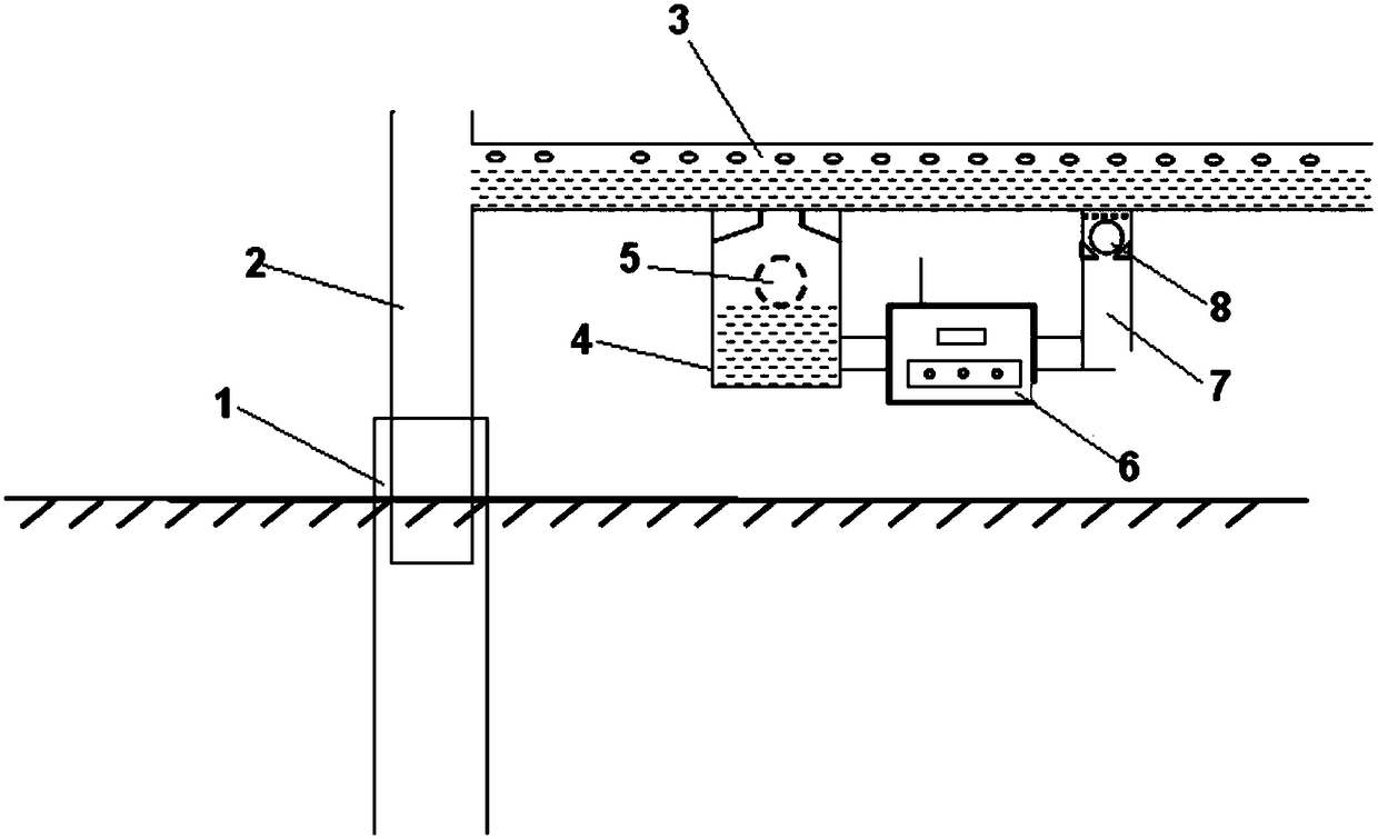
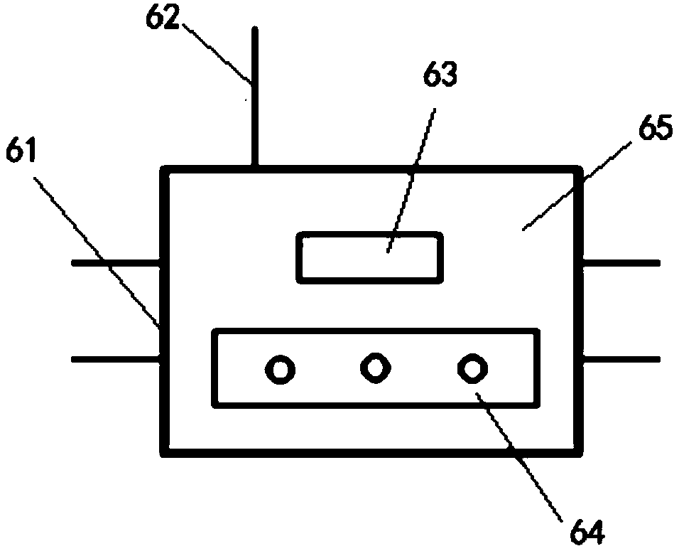
[0032] Such as figure 1 As shown, an automatic test device for water content at the wellhead of an oil well provided by an embodiment of the present invention includes an oil storage tank 4, a floating ball plug 5, a water content tester 6, a return pipe 7 and a check valve 8;

[0033] The oil storage tank 4 is provided with a liquid inlet hole, the liquid inlet hole communicates with the oil well pipeline manifold 3, and the other end communicates with the input end of the water content tester 6, the oil storage tank 4 is located below the oil well pipeline manifold 3, the return pipe 7 and the water content The output end of the tester 6 is connected; the water content tester 6 is provided with a power device, and the power device is used to transport the liquid in the oil storage tank to t...


PUM


Abstract

The invention discloses an oil well wellhead water content automatic test device and a test method thereof. By means of the method, the water content of an oil-water mixture can be conveniently and rapidly measured at a wellhead to achieve fine monitoring of yield fluctuation of oil wells of an oil field and rapid monitoring of the water content of the oil wells. The device comprises an oil storage box, a floating ball plug, a water content measuring instrument, a back flowing tube and a one-way valve; the oil storage box is communicated with an oil well oil delivery manifold through a formedliquid inlet, and the oil storage box is located below the oil well oil delivery manifold; the input end of the water content measuring instrument is communicated with the oil storage box, and the output end is connected with the back flowing tube; a power device is arranged in the water content measuring instrument, and the power device is used for delivering the liquid in an oil storage tank tothe oil well oil delivery manifold through the back flowing tube; the floating ball plug is arranged in the oil storage box, and the density of the floating ball plug is smaller than oil; the one-wayvalve is arranged between the back flowing tube and the oil well oil delivery manifold, and the back flowing tube is communicated with the oil well oil delivery manifold in one direction from the backflowing tube to the oil well oil delivery manifold by means of the one-way valve.

Description

technical field [0001] The invention relates to the technical field of oil recovery in oil fields, in particular to an automatic testing device and a testing method for water content at the wellhead of an oil well. Background technique [0002] At present, in the production wells of all oil fields in the world, the production fluid of the oil well contains a certain proportion of produced water. In order to monitor the production water of the oil well in real time and accurately grasp the oil production of the oil well, each oil field must measure regularly The water content of the oil well produced fluid, because the water content of the liquid in the formation is changing, so the monitoring of the water content of the oil well is an important task in the daily production of the oil field. [0003] Usually, during normal production, the water cut of oil wells in the oil field needs to be measured every 10 days, and the monitoring period of some wells with large water cut fl...

Claims


Application Information

Patent Timeline
IPC IPC(8): G01N33/28
CPCG01N33/2847
Inventor 刘涛周志平甘庆明陆梅李大建辛宏张岩韩二涛周杨帆
Owner PETROCHINA CO LTD
Learn More