
Wellhead oil-gas-water three-phase flow impedance-capacitance type water content measuring device and method

A capacitance water content and measuring device technology, which is applied in the direction of measurement, mining fluid, earthwork drilling, etc., can solve the problems of inability to realize automatic measurement, large difference in accuracy, poor measurement effect, etc., and achieve real-time online measurement, safety High and long service life effect

Active Publication Date: 2019-06-21
YANSHAN UNIV
View PDF11 Cites 6 Cited by
  • Summary
  • Abstract
  • Description
  • Claims
  • Application Information

AI Technical Summary

Problems solved by technology

However, at present, the conductivity method needs to obtain the dynamic full water phase correction value in the oil well in advance, and cannot realize automatic measurement. The capacitance method is mainly aimed at the dynamic measurement in the case of low water cut with high accuracy, and the measurement effect in the high water cut area is extremely poor. At the same time, the conductivity method and the capacitance method are easily affected by the gas phase conditions, and the accuracy is quite different.
[0004] At present, a variety of multi-parameter oil, gas and water three-phase flow measurement devices for land surface wellheads have been developed at home and abroad, but they are expensive, bulky, and complicated to work. The basic conditions of the oilfield, such as wide, large demand, and frequent field measurements

Method used


Image

  • Wellhead oil-gas-water three-phase flow impedance-capacitance type water content measuring device and method
  • Wellhead oil-gas-water three-phase flow impedance-capacitance type water content measuring device and method
  • Wellhead oil-gas-water three-phase flow impedance-capacitance type water content measuring device and method

Examples


Embodiment 1

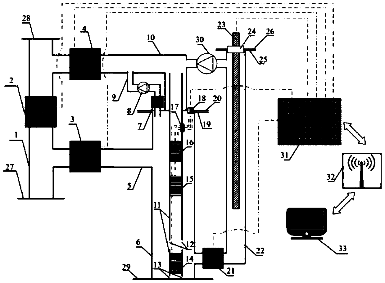
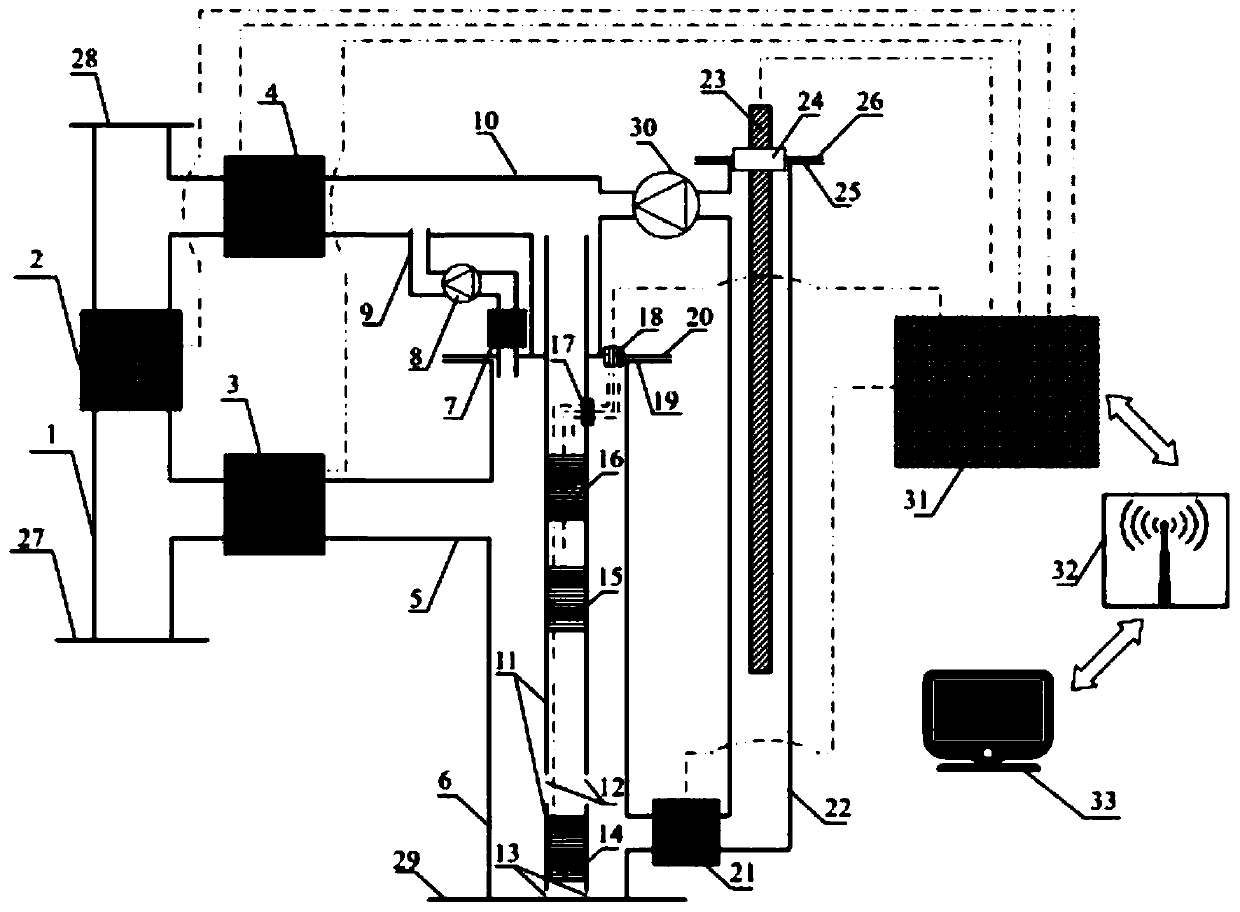
[0043] A wellhead oil-gas-water three-phase flow impedance capacitance water cut measurement device and method, such as figure 1 As shown, the water cut measurement device includes a wellhead installation module, a gas-liquid separation system, a dynamic water cut measurement system, a static water cut measurement system, a control valve group and a data processing system. Wherein, the wellhead installation module includes an installation pipeline 1, an installation pipeline inlet flange 27, an installation pipeline outlet flange 28, and the installation pipeline inlet flange 27 and the installation pipeline outlet flange 28 are respectively welded to both ends of the installation pipeline 1;

[0044] The gas-liquid separation system includes a mixed-phase inlet pipeline 5, a gas-liquid separation tank 6, a gas-liquid separation tank base 29, a first flange 19 on the top of the gas-liquid separation tank, a second flange 20 on the top of the gas-liquid separation tank, a connec...

Embodiment 2

[0050] In the wellhead installation module, the first control valve 2 is sealed and installed in the middle of the installation pipeline 1, and the liquid inlet of the second control valve 3 is sealed and connected between the first control valve 2 and the inlet flange 27 of the installation pipeline through the pipeline. A control valve 2 and the outlet flange 28 of the installation pipeline are sealed and connected to the liquid outlet of the third control valve 4 through a pipeline.

[0051] In the gas-liquid separation module, one end of the mixed-phase inlet pipe 5 is sealed and connected with the liquid outlet of the second control valve 3, and the other end is sealed and connected with the gas-liquid separation tank 6; one end of the mixed-phase outlet pipe 10 is sealed and connected with the liquid inlet of the third control valve 4 , the other end of the mixed-phase outlet pipe 10 is welded on the second flange 20 on the top of the gas-liquid separation tank; one end o...

Embodiment 3

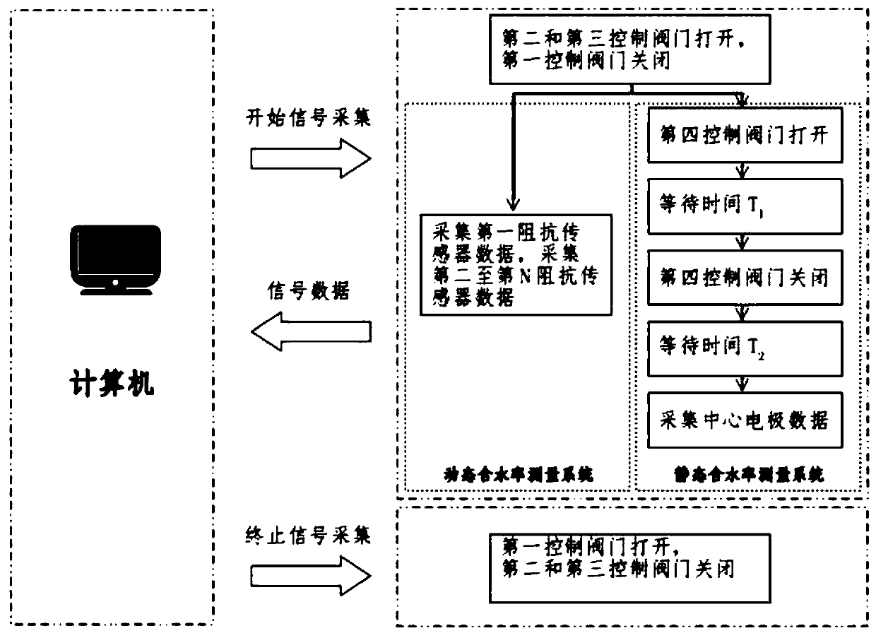
[0055] A control method of a wellhead oil-gas-water three-phase flow impedance capacitance water content measuring device, manually send out start signal acquisition and termination signal acquisition instructions through a computer 33, the wellhead circuit system 31 receives the instructions from the computer 33 from a wireless base station 32, and controls the Control the on-off of the valve group to control the internal fluid flow of the measuring device, and perform signal collection and transmission; the control method includes:

[0056] like figure 2 As shown, when the wellhead circuit system 31 receives the instruction to start signal collection from the computer 33, the wellhead circuit system 31 controls the opening of the second control valve 3, the third control valve 4, and the fourth control valve 21, and the first control valve 2 Close; the oil-gas-water multiphase fluid flows through the installation pipeline inlet flange 27, the second control valve 3, and the...


PUM


Abstract

The invention relates to a wellhead oil-gas-water three-phase flow impedance-capacitance type water content measuring device and method. The device comprises a wellhead installation module, a gas-liquid separation system, a dynamic water content measuring system, a static moisture content measuring system, a control valve group and a data processing system; and during the measurement, the oil-gas-water three-phase flow is firstly subjected to gas-liquid separation in the gas-liquid separation system, a gas phase is discharged from a gas phase outlet pipeline, a liquid phase flows through the dynamic water content measuring system and the static moisture content measuring system separately, and dynamic and static water content measurement is carried out. The device and the method have the advantages of being high in sensitivity, reliable in measurement, low in cost, long in service life and high in safety, the problem that the water content data can be obtained only after a sample is taken at a wellhead of an oil well and then is transported to a central laboratory for the process of testing and the like in the traditional production process can be solved, and efficient real-time monitoring of the oil production rate of the oil well is realized.

Description

technical field [0001] The invention relates to a land surface wellhead water content measuring device and a control method, in particular to a land surface wellhead water content measuring device and method for measuring impedance capacitance water content of three-phase flow of oil, gas and water at the land surface wellhead. Background technique [0002] In the deep storage area of ​​oil wells, the gas is mainly natural gas, hydrocarbon and non-hydrocarbon gas, which mainly exists in the crude oil in the form of dissolved gas. As the crude oil flows upward, the gas gradually precipitates as the pressure decreases. , at the wellhead of the oil well, there will be a phenomenon that the three phases of oil, gas and water coexist. With the development of computer technology and network technology, promoting the digitalization of oilfield production has become the primary development strategy of oilfield construction, but the automatic measurement of water cut parameters of si...

Claims


Application Information

Patent Timeline
IPC IPC(8): E21B47/00E21B49/08E21B43/34
Inventor 孔德明陈基亮李军孔维航袁丽田小强谢贝贝崔耀耀孔令富郝虎吴伟超何大川
Owner YANSHAN UNIV
Learn More