Control system and control method for rotary positioning platform under microscope

A positioning platform, a technology under the microscope, applied in the field of microscopy, can solve the problems of large displacement change of the sample, failure of sample imaging and operation, fluctuation of radial displacement of the sample, etc., to improve the accuracy of rotation positioning and improve the effect of microscopic imaging.

Active Publication Date: 2021-04-27
GUANGDONG MINGKAI MEDICAL ROBOTS CO LTD
View PDF6 Cites 0 Cited by
  • Summary
  • Abstract
  • Description
  • Claims
  • Application Information

AI Technical Summary

Problems solved by technology

Compared with linear positioning, rotational positioning has very strict requirements on the micro-nano operating system, because if the sample has a small amount of eccentricity, a small rotation angle may cause a large displacement change of the sample under the microscope
It is very difficult to fit the sample at the absolute center of rotation in real practice
In addition, even small natural vibrations of the micro-nano robot operating platform will lead to obvious radial displacement fluctuations of the sample at the micro-nano scale
Therefore, for the rotating micro-nano operating platform, the radial fluctuation of the sample always exists when the sample is rotated under the microscope. The fluctuation characteristics of these samples will inevitably bring about image blurring, deformation, and even make the sample move out of the observation field of the microscope, resulting in sample imaging. and the failure of the operation
Therefore, the high-precision positioning of the rotating sample is still the bottleneck of highly flexible micro-nano manipulation in the microscope environment.

Method used


Image

  • Control system and control method for rotary positioning platform under microscope
  • Control system and control method for rotary positioning platform under microscope
  • Control system and control method for rotary positioning platform under microscope

Examples


Embodiment Construction

[0044] The present invention will be further described in detail below in conjunction with the accompanying drawings and embodiments. It should be understood that the specific embodiments described here are only used to explain the present invention, but not to limit the present invention. In addition, it should be noted that, for the convenience of description, only some structures related to the present invention are shown in the drawings but not all structures.

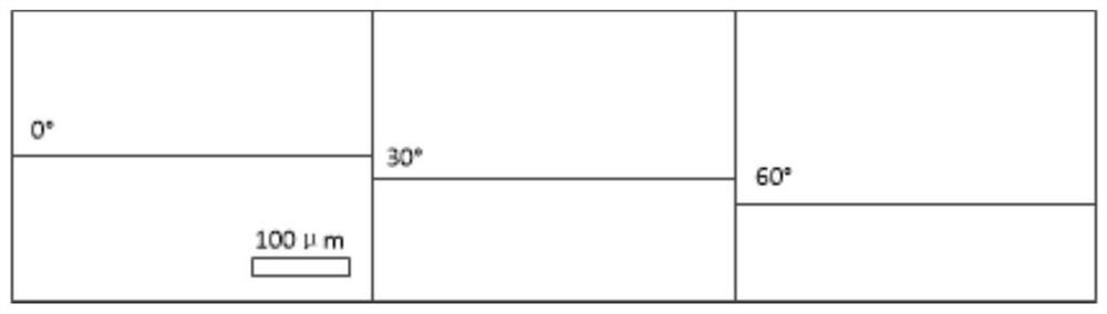
[0045] Microscopes can already observe samples at the micro-nano scale. Due to the high requirements for the operation and control precision of samples under the microscope at the micro-nano scale, it is necessary to study the operating system with micro-nano precision. At present, for samples with linear motion, there are already many operating systems that can achieve micro-nano precision operations. However, for the observation of rotating samples, there is no operating system with micronano precision that can ...


PUM


Abstract

The invention discloses a control system and a control method of a rotary positioning platform under a microscope. The system includes: a rotary console, first and second translation consoles, a sample stage, a visual feedback subsystem, a driver, and a double closed-loop positioning Control system, the movement directions of the first and second translation consoles are perpendicular to the rotation axis of the rotary console; the double closed-loop positioning control system includes: the external position controller calculates the input displacement of the inner ring; the first and second translation control The displacement closed-loop control subsystem of the table includes: the plug-in repetitive controller calculates the displacement compensation control quantity according to the error between the input displacement and the feedback displacement; the original closed-loop displacement control subsystem calculates the displacement control quantity according to the error between the input displacement and the feedback displacement , and combined with the displacement compensation control amount to control the driver to drive the displacement of the first and second translation consoles. Improve the rotational positioning accuracy of micro-nano-scale samples under the microscope, and greatly improve the microscopic imaging effect of the sample.

Description

technical field [0001] Embodiments of the present invention relate to microscope technology, and in particular to a control system and method for a rotary positioning platform under a microscope. Background technique [0002] With the rapid development of micro-nano technology, the sample positioning technology at the microscopic scale, as one of the key technologies for precise imaging under the microscope and in situ precise characterization, has attracted more and more attention. Different from the macroscopic scale at the microscopic scale, samples in the microscope environment face some unique challenges, including narrow working space, limited observation field, and few sensing methods and unknown depth information. Therefore, the demand for high-precision positioning at the micro-nano scale has brought new requirements to traditional micro-nano operating systems and technologies. [0003] At present, most micro-nano manipulators can only observe linearly moving sampl...

Claims


Application Information

Patent Timeline
Patent Type & Authority Patents(China)
IPC IPC(8): G05D3/12G02B21/32
CPCG02B21/32G05D3/12
Inventor 尚万峰王春宝刘铨权段丽红申亚京
Owner GUANGDONG MINGKAI MEDICAL ROBOTS CO LTD
Why Eureka
Try Eureka