
A mechanical mechanism and control system of a pneumatic handling manipulator

A mechanical mechanism and control system technology, applied in the direction of manipulators, program-controlled manipulators, manufacturing tools, etc., can solve the problems of high cost and low positioning accuracy of oscillating cylinders, and achieve low cost, strong anti-interference ability and stability, and high operating speed fast effect

Inactive Publication Date: 2016-09-14
JIANGSU UNIV
View PDF5 Cites 0 Cited by
  • Summary
  • Abstract
  • Description
  • Claims
  • Application Information

AI Technical Summary

Problems solved by technology

However, some workplaces only need to reciprocate the parts between two points. The positioning accuracy of the manipulator using the pneumatic servo system is high. Although it can complete related functions, the cost is relatively high.
If the mechanical arm of the pneumatic manipulator wants to achieve a certain angle of rotation, it needs to use a swing cylinder, and the positioning accuracy of the swing cylinder is generally not high, and it cannot perform high-precision positioning

Method used


Image

  • A mechanical mechanism and control system of a pneumatic handling manipulator
  • A mechanical mechanism and control system of a pneumatic handling manipulator
  • A mechanical mechanism and control system of a pneumatic handling manipulator

Examples


Embodiment Construction

[0022] The following will clearly and completely describe the technical solutions in the embodiments of the present invention with reference to the drawings in the embodiments of the present invention.

[0023] In describing the present invention, it should be understood that the terms "center", "longitudinal", "transverse", "upper", "lower", "front", "rear", "left", "right", " The orientations or positional relationships indicated by "vertical", "horizontal", "top", "bottom", "inner" and "outer" are based on the orientations or positional relationships shown in the drawings, and are only for the convenience of describing the present invention and Simplified descriptions, rather than indicating or implying that the device or element referred to must have a particular orientation, be constructed and operate in a particular orientation, and thus should not be construed as limiting the invention. In addition, the terms "first" and "second" are used for descriptive purposes only, ...


PUM


Abstract

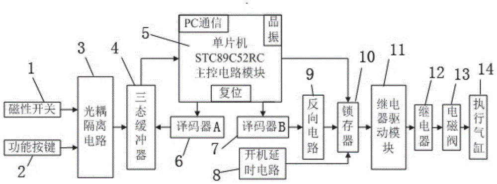
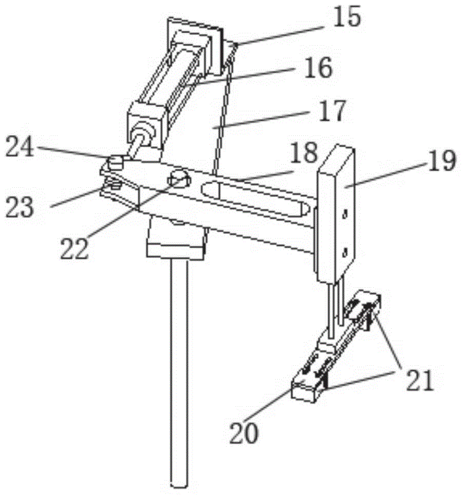
The invention relates to a mechanical mechanism and control system of a pneumatic handling mechanical hand, and belongs to the field of pneumatic handling mechanical hands. The mechanical mechanism of the pneumatic handling mechanical hand comprises the relevant connection relation of a horizontal telescopic air cylinder fixing seat, a horizontal telescopic air cylinder, a horizontal supporting seat, a rotary arm, a vertical lifting air cylinder, a clawing claw fixing seat, clamping claws, a rotary shaft and a connector I. The control system comprises a magnetic switch, a function key, an opto-isolator circuit, a three-state buffer, a single-chip microcomputer STC89C52RC master control circuit module, a decoder, a starting delay circuit, a reverse circuit, a latch, a relay drive module, a relay, an electromagnetic valve and an execution air cylinder. The designed pneumatic handling mechanical hand is easy to achieve, accurate in locating and high in economic efficiency, can be switched between two work stations, and is especially suitable for point location handling of injection molding blades in air conditioners.

Description

technical field [0001] The invention relates to a mechanical structure and control system of a pneumatic transport manipulator, which belongs to the field of pneumatic transport manipulators. It is a mechanical structure and control circuit of a pneumatic transport manipulator with accurate positioning and easy implementation, and is especially suitable for point transport of injection-molded blades in air conditioners. . Background technique [0002] Traditional manipulator applications mostly use electric servo drive, because electric servo technology has gone through a long period of development and has become a very mature technology (Yang Zhenqiu, Research and application of simple and precise positioning pneumatic manipulator[ D] Wuhan: Huazhong University of Science and Technology, 2006). The driving motor generally adopts stepping motor, AC and DC servo motor, etc. The manipulator with electric drive is characterized by large driving force, very high control precis...

Claims


Application Information

Patent Timeline
Patent Type & Authority Patents(China)
IPC IPC(8): B25J9/08B25J9/18
Inventor 宋寿鹏杨阳乔宗蹼
Owner JIANGSU UNIV
Learn More