Assembly head and automatic assembling machine

A technology of assembly heads and assembly machines, applied in the direction of electrical components, electrical components, etc., can solve problems such as adverse effects on positioning accuracy, and achieve the effects of small torque, small axial force, and high measurement accuracy

Active Publication Date: 2015-04-29
ASM ASSEMBLY SYST GMBH & CO
View PDF3 Cites 0 Cited by
  • Summary
  • Abstract
  • Description
  • Claims
  • Application Information

AI Technical Summary

Problems solved by technology

However, during the rotary movement of the vacuum suction tube, considerable torques are generated by the contact seal, which has a significant adverse effect on the positioning accuracy.

Method used


Image

  • Assembly head and automatic assembling machine
  • Assembly head and automatic assembling machine
  • Assembly head and automatic assembling machine

Examples


Embodiment Construction

[0030] In the different representations of the figures, the same components always bear the same reference numerals. This description applies to all figures in which corresponding parts can likewise be identified.

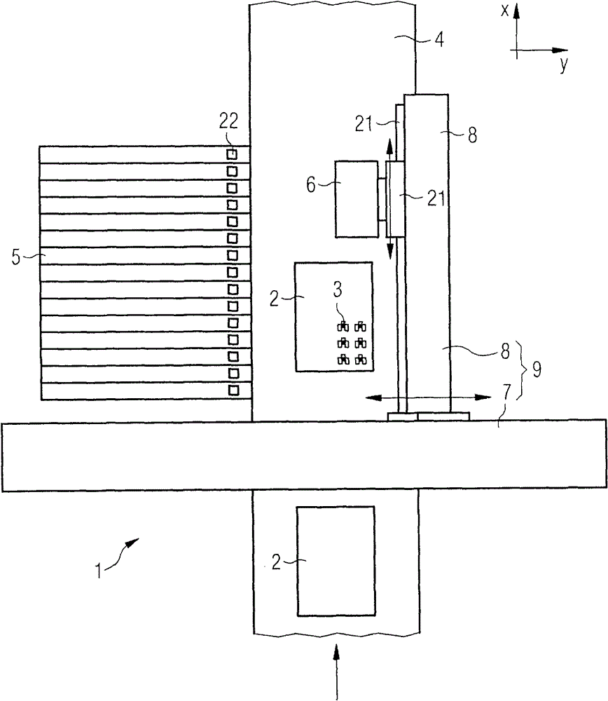
[0031] figure 1 The general structure of an automatic assembly machine 1 for assembling components 3 for substrates 2 is schematically shown, which is adapted to accommodate a mounting head 6 according to the invention. The automatic assembly machine 1 has a cross member 7 which extends in the y-direction and which is fixedly connected to a frame (not shown). Mounted on the crossbeam 7 is a mast arm 8 which extends in the x-direction and is fastened on the crossbeam 7 so that it can move in the y-direction. The crossbeam 7 and the mast arm 8 together form a positioning system 9 , wherein a Cartesian coordinate system is formed by the x-axis and the y-axis. Arranged on the mast arm 8 is a mounting head 6 which can be moved in the x-direction along the mast arm 8 ...


PUM


Abstract

The head has a mechanical arm (11) for picking and holding a member (3), and a pneumatic unit (12) for loading preset pressure (p1) to the mechanical arm. A pneumatic tube (13) is mounted on an assembly head. Another pneumatic tube (14) is partially guided in an interior of the mechanical arm and connected with the former pneumatic tube. The pneumatic tubes are used as rigid connecting tubes and mutually plugged on connecting positions (A-B) to be connected. A flow rate sensor determines a volume flow in the former pneumatic tube.

Description

technical field [0001] The invention relates to a mounting head for mounting components to a substrate and to an automatic mounting machine with a mounting head of this type. Background technique [0002] In assembly technology, components are assembled by means of automatic assembly machines as substrates, in most cases printed circuit boards. For this purpose, mounting heads are usually used, which are movable in a plane parallel to the plane of the substrate by means of a positioning system of the automatic assembly machine and are designed to pick up components or to position them on the substrate. With the aid of assembly heads designed in this way, components from so-called feeders are picked up and conveyed to the assembly area of ​​the automatic assembly machine, where the substrates to be assembled are provided and assembled to predetermined assembly position. [0003] Today, for the assembly of printed circuit boards, the SMT method (Surface Mount Technology) is ...

Claims


Application Information

Patent Timeline
Patent Type & Authority Patents(China)
IPC IPC(8): H05K13/04
CPCH05K13/0409H05K13/082
Inventor 斯特凡·布格尔
Owner ASM ASSEMBLY SYST GMBH & CO
Why Eureka
Try Eureka