Hollow parallel harmonic reduction device and driving method thereof

A technology of harmonic deceleration and harmonic reducer, which is applied to transmission devices, transmission device parts, belts/chains/gears, etc., and can solve problems such as insufficient torsional rigidity and poor rotational positioning accuracy of harmonic reducers

Inactive Publication Date: 2021-07-06
江苏镌极特种设备有限公司
View PDF4 Cites 0 Cited by
  • Summary
  • Abstract
  • Description
  • Claims
  • Application Information

AI Technical Summary

Problems solved by technology

[0004] Therefore, the technical problem to be solved by the present invention is to overcome the technical defects

Method used


Image

  • Hollow parallel harmonic reduction device and driving method thereof
  • Hollow parallel harmonic reduction device and driving method thereof

Examples


Embodiment Construction

[0030] The present invention will be further described below in conjunction with the accompanying drawings and specific embodiments, so that those skilled in the art can better understand the present invention and implement it, but the examples given are not intended to limit the present invention.

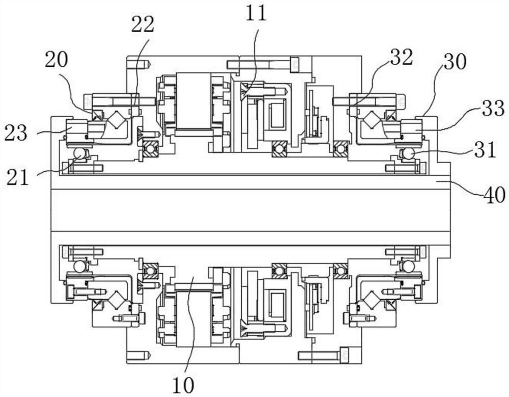
[0031] refer to figure 1 As shown, the hollow parallel harmonic reduction device of the present invention includes a hollow shaft 10 , a harmonic reduction assembly and an output shaft 40 .

[0032] The hollow shaft 10 can rotate around its central axis, and the hollow shaft 10 is provided with a first hollow hole. The harmonic reduction assembly is arranged on the outer wall of the hollow shaft 10 , and the harmonic reduction assembly includes a first harmonic reduction gear 20 and a second harmonic reduction gear 30 distributed along the axial direction of the hollow shaft 10 . The output shaft 40 is located in the first hollow hole, and the output shaft 40 is connected with th...


PUM


Abstract

The invention relates to a hollow parallel harmonic reduction device and a driving method thereof. The harmonic reduction device comprises a hollow shaft, a harmonic reduction assembly and an output shaft, wherein the hollow shaft can rotate around the central axis thereof, and a first hollow hole is formed in the hollow shaft; the harmonic reduction assembly is arranged on the outer side wall of the hollow shaft and comprises a first harmonic reducer and a second harmonic reducer which are distributed in the axial direction of the hollow shaft; the output shaft is located in the first hollow hole and is connected with the harmonic reduction assembly to achieve power output of the harmonic reduction assembly; and the hollow shaft drives the first harmonic reducer and the second harmonic reducer to work synchronously, the first harmonic reducer and the second harmonic reducer transmit power to the output shaft, and the output shaft outputs the power. The harmonic reduction device can obtain higher rotary positioning precision and higher torsional rigidity, and is good in synchronism, compact in structure and good in stability.

Description

technical field [0001] The invention relates to the technical field of reducers, in particular to a hollow parallel harmonic reducer and a driving method thereof. Background technique [0002] The unique advantages of high load capacity, large transmission ratio, small size, stable transmission and high transmission precision make harmonic reducers widely used in electronics, aerospace, robotics and other industries. [0003] The existing harmonic reducer is arranged on the power output shaft of the driving source, and the power is transmitted through the harmonic reducer. However, when the load is too heavy, the torsional rigidity of the harmonic reducer is often not enough, and the rotation positioning accuracy is poor. Contents of the invention [0004] Therefore, the technical problem to be solved by the present invention is to overcome the technical defects of poor rotational positioning accuracy and insufficient torsional rigidity of the harmonic reducer in the prio...

Claims


Application Information

Patent Timeline
IPC IPC(8): F16H49/00F16H35/18F16H57/023
CPCF16H49/001F16H35/18F16H57/023
Inventor 赵言正李健伟
Owner 江苏镌极特种设备有限公司
Why Eureka
Try Eureka