
Method for generating two-dimensional layout diagram of three-dimensional bridge model by using CATIA software

A bridge model and layout technology, applied in geometric CAD, special data processing applications, instruments, etc., can solve problems such as hindering the application of CATIA software, difficult to handle two-dimensional drawings, and overlapping structural lines.

Active Publication Date: 2018-09-21
SHANGHAI URBAN CONSTR DESIGN RES INST GRP CO LTD
View PDF3 Cites 5 Cited by
  • Summary
  • Abstract
  • Description
  • Claims
  • Application Information

AI Technical Summary

Problems solved by technology

Moreover, most of the drawings produced in the field of mechanical engineering are detailed drawings of components and general assembly drawings, and the graphics area is usually a rectangle or a rectangle with an aspect ratio of no more than 2:1. Elevation General Arrangement)" or "Front Plan General Arrangement" is a drawing in which the length direction of the figure is much larger than the width direction (the aspect ratio is greater than 2:1)
[0003] Therefore, bridge designers can only refer to the existing CATIA drawing methods to make bridge component drawings and partial large-scale drawings, but they cannot solve the problem of converting the overall model of the bridge with a large aspect ratio established in CATIA software from "3D graphics" to " Publishing Issues of Drawings in Two-dimensional Graphics
In addition, the direct projection bridge model also has the problem of overlapping structural lines, which is difficult to handle for 2D maps
[0004] The existence of the above problems hinders the application of CATIA software in the field of bridge engineering. Therefore, it is necessary to propose a method that can provide complete design information for the production of two-dimensional graphics on the premise of ensuring the integrity of the overall model of the bridge.

Method used


Image

  • Method for generating two-dimensional layout diagram of three-dimensional bridge model by using CATIA software

Examples


Embodiment

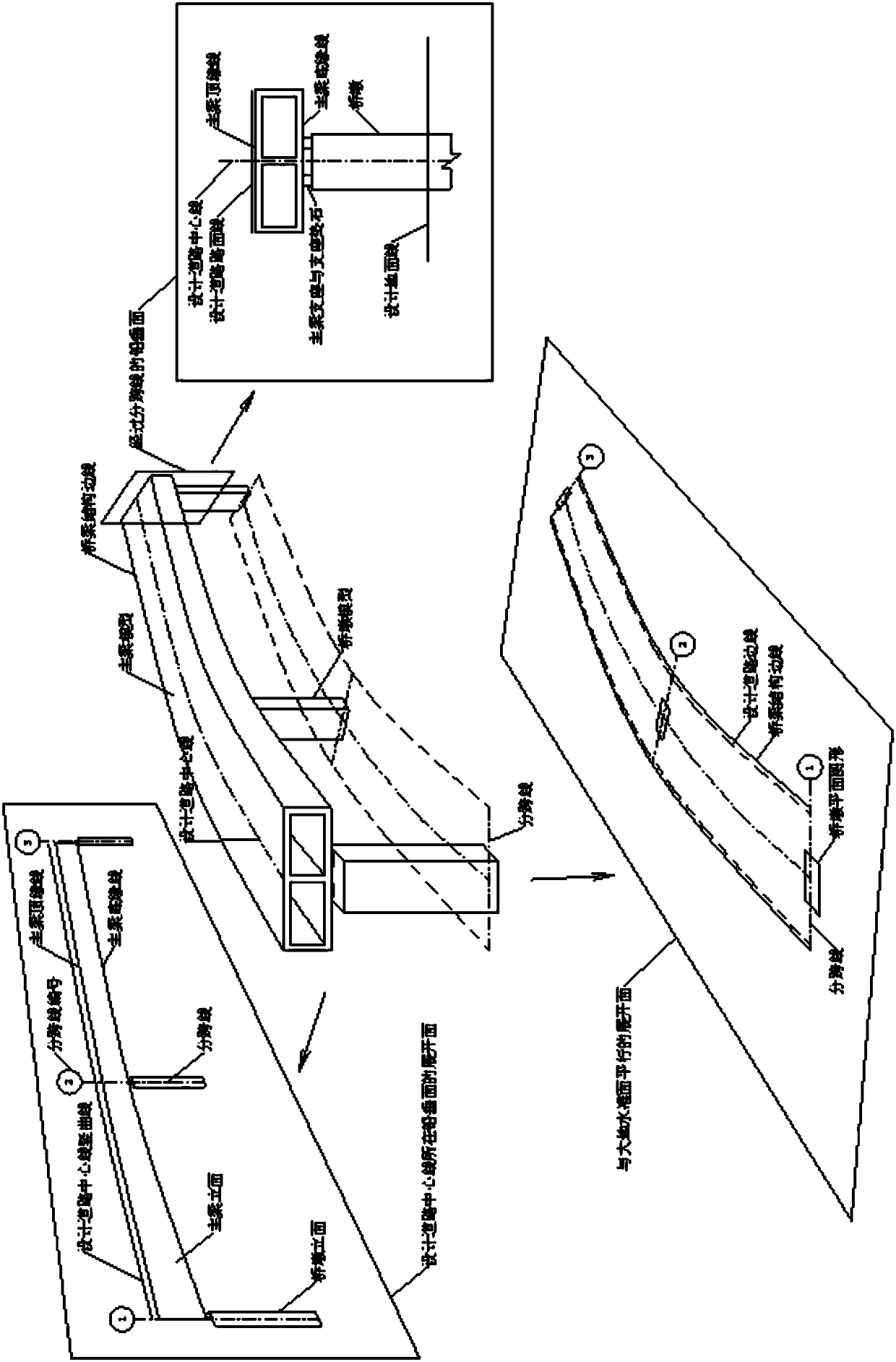
[0023] Such as figure 1 As shown, the method of using CATIA software to generate a two-dimensional layout drawing from a three-dimensional bridge model; the steps are as follows:

[0024] a. Receive the data of the designed road in the CATIA software, which includes the vertical curve of the designed road centerline, the horizontal curve of the designed road centerline, the left and right side plane edges of the left and right sides of the designed road, and the transverse slope of the designed road Information, design ground vertical curve at centerline of design road;

[0025] b. According to the road data received in step a, establish a three-dimensional model of the bridge in CATIA software, and store all key design information of the bridge structure in the three-dimensional model space in the form of parameters and design tables in the CATIA software , forming the core database;

[0026] c. Use the user-defined feature UDF in the CATIA software to make a two-dimensiona...


PUM


Abstract

The present invention discloses a method for generating a two-dimensional layout diagram of a three-dimensional bridge model by using CATIA software. The method comprises the following steps: receiving data for designing a road in the CATIA software, establishing a three-dimensional model of the bridge, and storing all key design information in a parameter form and a design list form in the CATIAsoftware into the three-dimensional model space; making a two-dimensional graphic template by using the user-defined feature UDF in the CATIA software; in the three-dimensional model space where the overall bridge model is located, generating a vertical unfolding surface corresponding to the vertical hook surface where the center line of the road is located, a horizontal unfolding surface parallelto the geoidal surface, and a plurality of vertical surfaces passing through the sub-line; and projecting the corresponding information respectively to generate a layout diagram of each surface of the bridge in the traditional two-dimensional drawing. According to the method provided by the present invention, information in the three-dimensional graph can be effectively transmitted to the two-dimensional graph, and data synchronization and model linkage can be realized.

Description

technical field [0001] The invention relates to the technical field of computer-aided design, in particular to a method for generating a two-dimensional layout drawing from a three-dimensional bridge model by using CATIA software. Background technique [0002] CATIA software is usually used for three-dimensional modeling in the field of mechanical engineering, and is rarely used for making two-dimensional drawings. Moreover, most of the drawings produced in the field of mechanical engineering are detailed drawings of components and general assembly drawings, and the graphics area is usually a rectangle or a rectangle with an aspect ratio of no more than 2:1. Elevation General Arrangement)" or "Front Plan General Arrangement" is a drawing in which the length direction of the figure is much larger than the width direction (the aspect ratio is greater than 2:1). [0003] Therefore, bridge designers can only refer to the existing CATIA drawing methods to make bridge component d...

Claims


Application Information

Patent Timeline
IPC IPC(8): G06F17/50
CPCG06F30/13
Inventor 胡方健周良陆元春
Owner SHANGHAI URBAN CONSTR DESIGN RES INST GRP CO LTD
Learn More