
Lightning protection device in multilevel clearance series connection

A lightning protection device and gap technology, applied in circuit devices, emergency protection circuit devices, emergency protection circuit devices for limiting overcurrent/overvoltage, etc. Problems such as large dispersion of air gap discharge

Active Publication Date: 2018-09-21
XI AN JIAOTONG UNIV
View PDF6 Cites 2 Cited by
  • Summary
  • Abstract
  • Description
  • Claims
  • Application Information

AI Technical Summary

Problems solved by technology

For gapless metal oxide surge arresters, which work under high power frequency overvoltage for a long time, they are prone to damage or explosion due to limited flow capacity; for single air gap series metal oxide surge arresters, although there is a single gap isolation , the arrester body only works when lightning strikes, prolonging the service life of the arrester, but the discharge dispersion of a single air gap is large, and the reliability of the arrester cannot be guaranteed
And for the above two current lightning protection methods, their breakdown voltage values ​​under the lightning impulse voltage are greater than their breakdown voltage values ​​under the power frequency voltage, that is, before the lightning protection device operates, the AC system needs to withstand Higher lightning impulse voltage peak value is detrimental to the normal operation of the AC system. In order to better protect the normal operation of the AC system, the lightning protection device should be able to operate and protect the AC system at a lower lightning voltage

Method used


Image

  • Lightning protection device in multilevel clearance series connection
  • Lightning protection device in multilevel clearance series connection
  • Lightning protection device in multilevel clearance series connection

Examples


Embodiment Construction

[0040]Specific embodiments of the present invention will be described in more detail below with reference to the accompanying drawings. While specific embodiments of the present invention are shown in the drawings, it should be understood that the present invention may be embodied in various forms and should not be limited by the embodiments set forth herein. Rather, these embodiments are provided so that a more thorough understanding of the present invention will be provided, and will fully convey the scope of the present invention to those skilled in the art.

[0041] It should be noted that certain terms are used in the description and claims to refer to specific components. It should be understood by those skilled in the art that the same component may be referred to by different nouns. The present specification and claims do not use the difference of nouns as a way of distinguishing components, but use the difference in function of the components as a criterion for disti...


PUM


Abstract

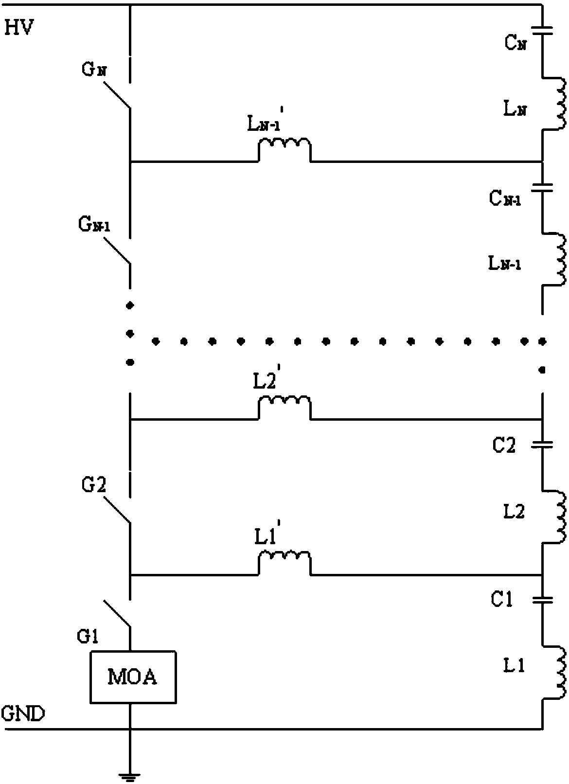
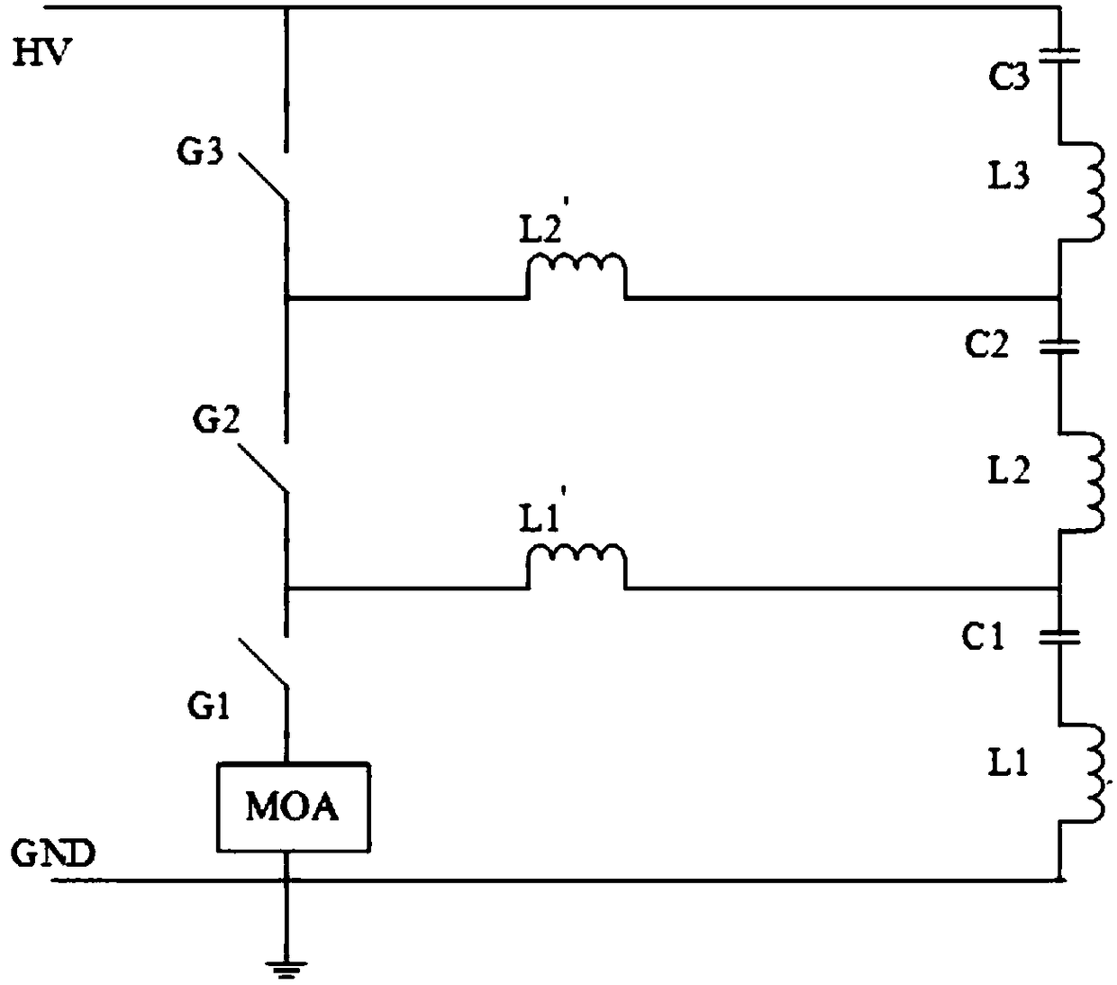
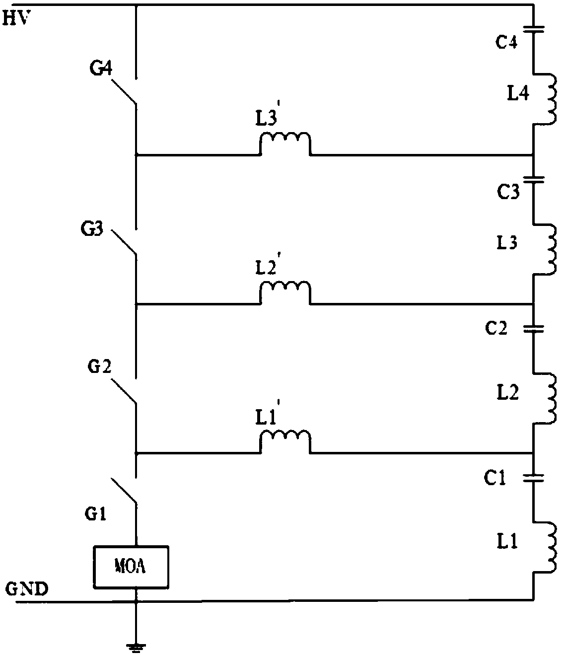
The invention discloses a lightning protection device in multilevel clearance series connection. The lightning protection device in multilevel clearance series connection includes a high-voltage wireinlet end, a grounding end, a metal oxide arrester (MOA), N voltage partition capacitors, N voltage partition inductors in series connection, N-1 loop voltage partition inductors and N discharging gaps at equal intervals. Since a multilevel clearance series connection structure is adopted, the lightning protection device can be resistant to high working-frequency voltage, and a breakdown voltage value of the lightning protection device under the working-frequency voltage is extremely higher than a breakdown voltage value under lightning impulse voltage. After clearances in multilevel series connection are broken down, the metal oxide arrester starts to work, wherein the metal oxide arrester (MOA) has the characteristics of generating no continuous current under work frequency. The lightning protection device has the advantages that not only is the breakdown voltage value of the lightning protection device under the working-frequency voltage extremely higher than the breakdown voltage value under the lightning impulse voltage, but also the lightning protection device is high in work reliability, free of continuous current under the working frequency and long in service life.

Description

technical field [0001] The invention relates to the technical field of electric power equipment, in particular to a lightning protection device connected in series with multi-level gaps. Background technique [0002] In the AC power system, lightning protection mainly uses lightning arresters for lightning protection. With the increase of transmission lines, the line trip accidents caused by lightning strikes are increasing day by day. Therefore, in order to reduce the line trip rate, under the premise of ensuring the protection performance, higher requirements are put forward for the long-term operation reliability of the arrester itself. [0003] At present, the arresters mainly used for line lightning protection have two structures: non-gap metal oxide arresters and single air gap series metal oxide arresters. For the gapless metal oxide arrester, it works under high power frequency overvoltage for a long time, and it is easy to be damaged or exploded due to the limited ...

Claims


Application Information

Patent Timeline
IPC IPC(8): H02H9/06
CPCH02H9/06
Inventor 杨兰均刘思炎李博睿郭海山
Owner XI AN JIAOTONG UNIV
Learn More