
Connecting rod control device

A control device and connecting rod technology, which is applied in the testing of measuring devices, instruments, vehicles, etc., can solve the problems of potential safety hazards, large geometric dimensions, and simultaneous work, and achieve the effect of convenient control, small size, and avoiding simultaneous work.

Pending Publication Date: 2018-09-25
SHANGHAI MOTOR VEHICLE INSPECTION CERTIFICATION & TECH INNOVATION CENT CO LTD
View PDF6 Cites 1 Cited by
  • Summary
  • Abstract
  • Description
  • Claims
  • Application Information

AI Technical Summary

Problems solved by technology

Due to the two motors, the device has a large geometry and a heavy weight
And because the two motors need to be controlled to work together, the cost will increase accordingly
In addition, there is a safety hazard that may cause the accelerator and brake pedals to work at the same time

Method used


Image

  • Connecting rod control device
  • Connecting rod control device
  • Connecting rod control device

Examples


Embodiment Construction

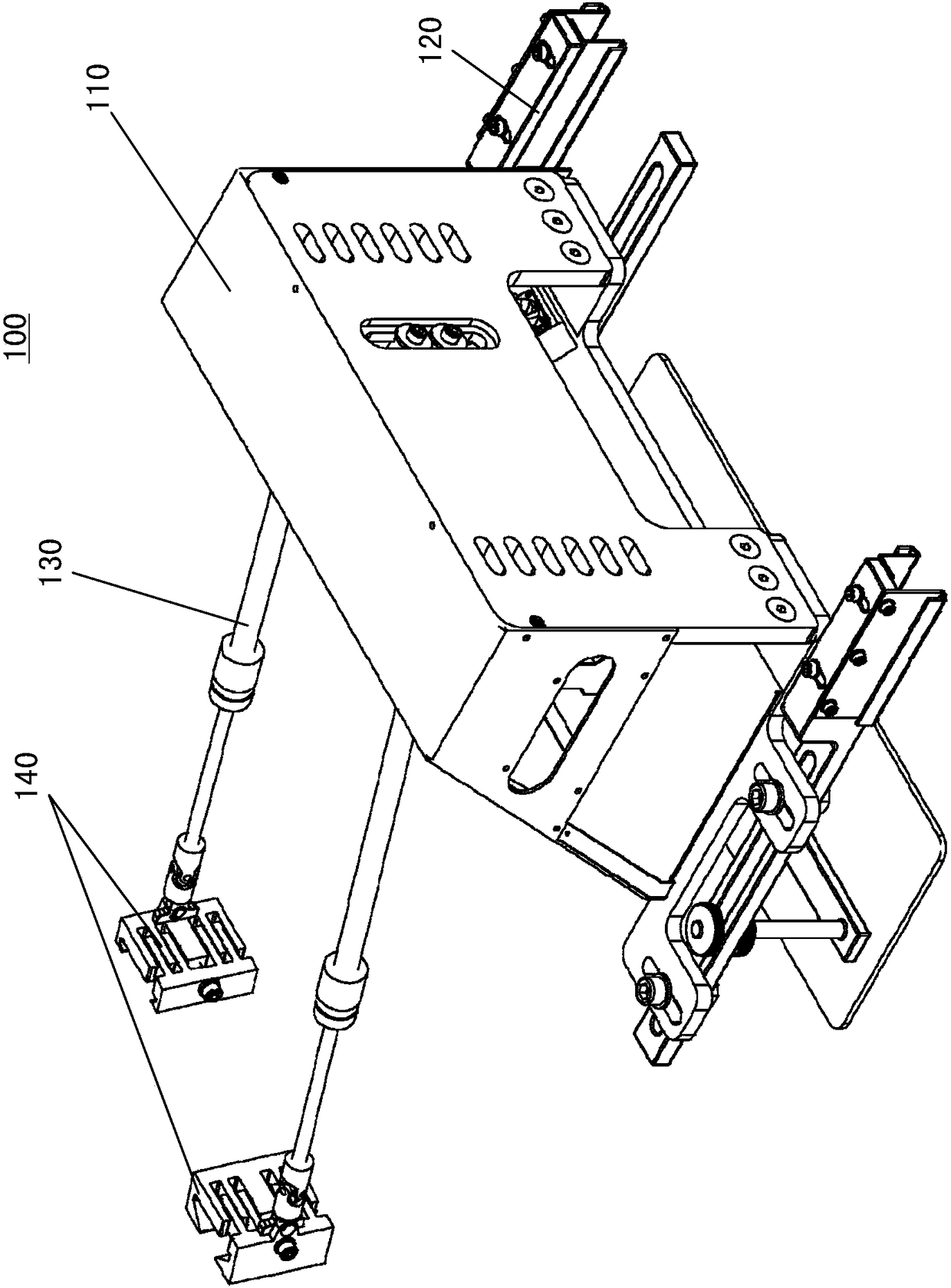
[0027] Embodiments of the present invention will now be described in detail with reference to the accompanying drawings. Reference will now be made in detail to the preferred embodiments of the invention, examples of which are illustrated in the accompanying drawings. Wherever possible, the same numbers will be used throughout the drawings to refer to the same or like parts. In addition, although the terms used in the present invention are selected from well-known and commonly used terms, some terms mentioned in the description of the present invention may be selected by the applicant according to his or her judgment, and the detailed meanings thereof are set forth herein described in the relevant section of the description. Furthermore, it is required that the present invention be understood not only by the actual terms used, but also by the meaning implied by each term.

[0028] figure 1 A schematic structural view of a vehicle testing device is shown. As shown in the fi...


PUM


Abstract

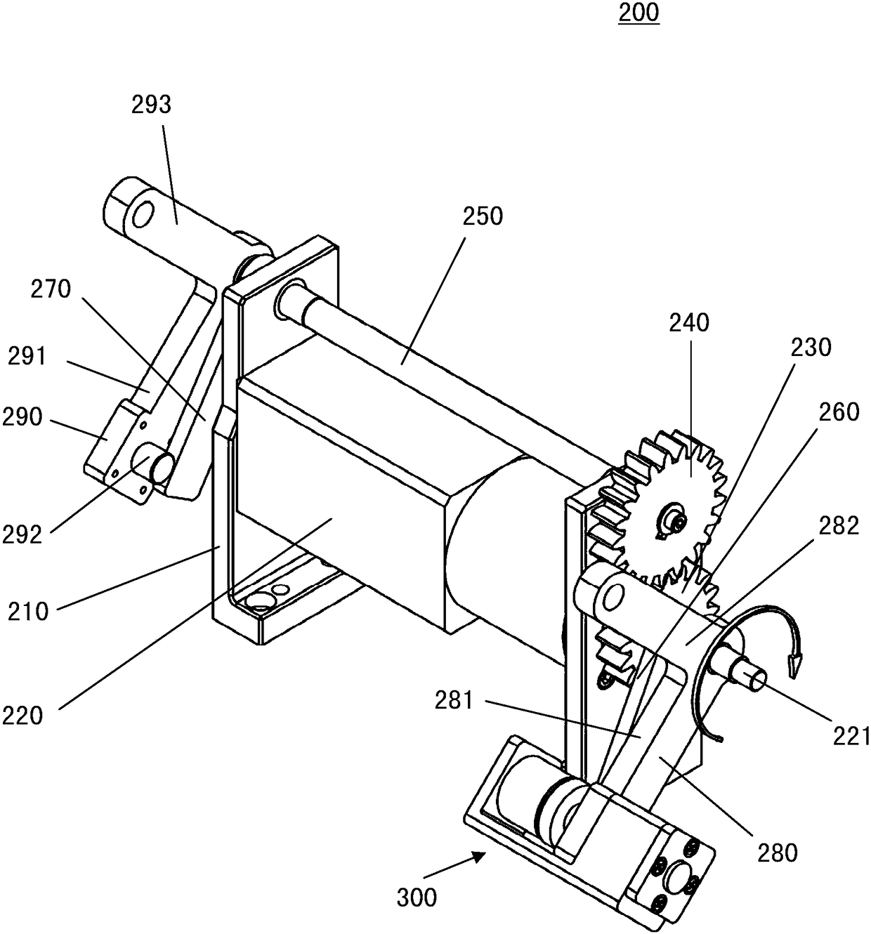
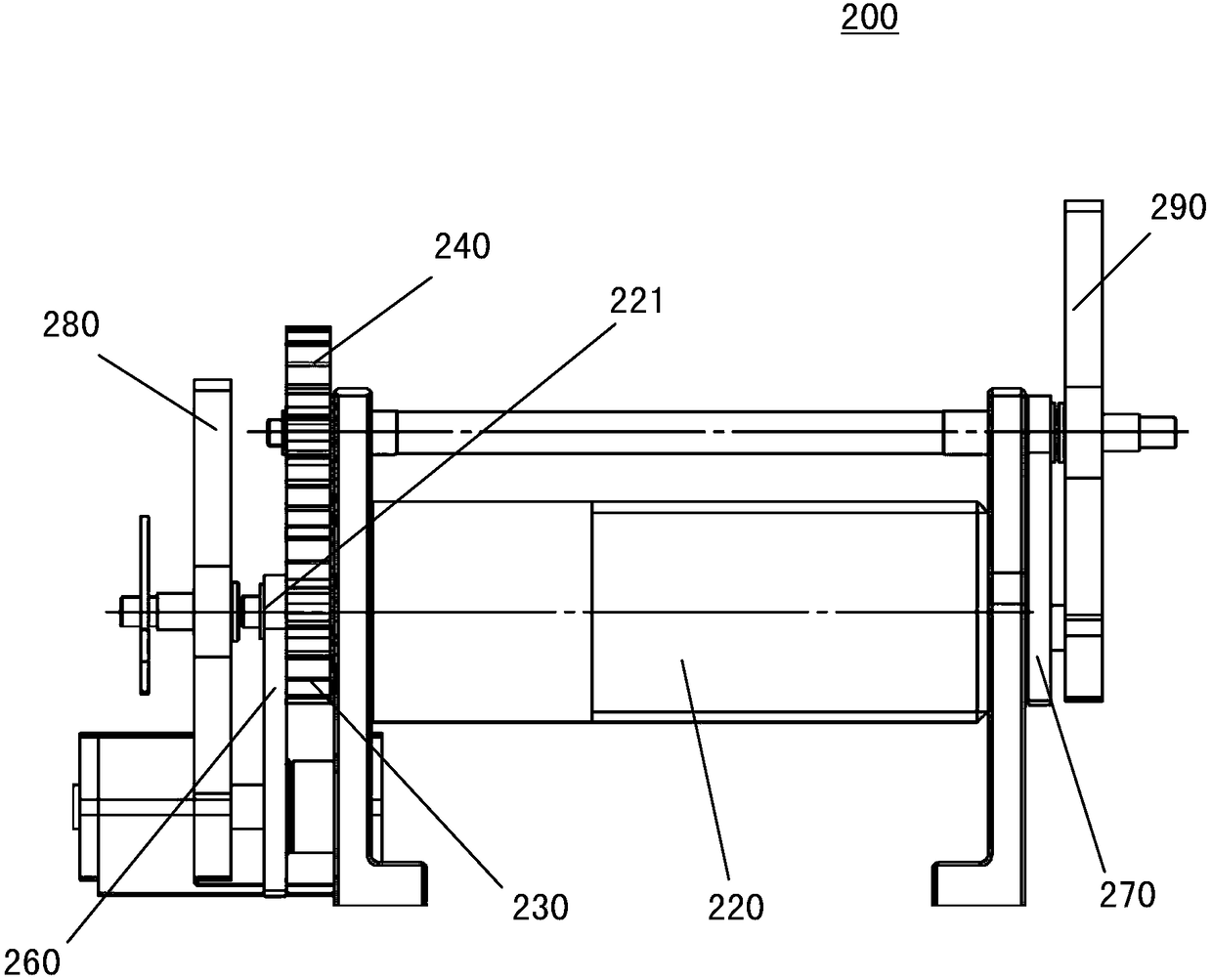
The invention relates to a connecting rod control device. The connecting rod control device includes a fixing base, a motor assembly, a first gear, a second gear, a link shaft, a first tumbler, a second tumbler, a first rotating disk, and a second rotating disk. The motor assembly is arranged on the fixing base. An output shaft of the motor assembly can drive the first gear and the first tumbler to rotate. The first gear is engaged with the second gear. The link shaft is arranged on the fixing base. One end of the link shaft is connected to the second gear. The second gear rotates to drive thelink shaft to rotate. The other end of the link shaft can drive the second tumbler to rotate. The rotating directions of the first tumbler and the second tumbler are opposite. The first tumbler can drive the first rotating disk to rotate. The second tumbler can drive the second rotating disk to rotate. The invention provides the connecting rod control device. The device is simple in overall structure, small in size, low in cost, and convenient in control, and can control an accelerator pedal and a brake pedal to orderly work.

Description

technical field [0001] The invention relates to the technical field of motor vehicles, in particular to a connecting rod control device suitable for motor vehicle detection equipment. Background technique [0002] The connecting rod control device is used in motor vehicle testing equipment, such as controlling the vehicle's accelerator pedal and brake pedal when the vehicle is undergoing a road condition simulation test, thereby simulating the state of the vehicle moving forward, accelerating, decelerating, and stopping. [0003] The existing connecting rod control device adopts two motors to control the accelerator pedal and the brake pedal respectively. Due to the two motors, the device has a large geometry and is heavy. And because it is necessary to control the two motors to work together, the cost is correspondingly increased. In addition, there is a safety hazard that may cause the accelerator pedal and brake pedal to work at the same time. Contents of the inventio...

Claims


Application Information

Patent Timeline
Patent Type & Authority Applications(China)
IPC IPC(8): G01M17/007
CPCG01M17/007
Inventor 丁珺
Owner SHANGHAI MOTOR VEHICLE INSPECTION CERTIFICATION & TECH INNOVATION CENT CO LTD
Learn More