Thermal resistance test circuit and method of reverse conduction type igbt

A test circuit, reverse conduction type technology, applied in the direction of single semiconductor device testing, measuring electricity, measuring electrical variables, etc., can solve the problem of low accuracy of thermal resistance testing

Active Publication Date: 2020-05-22
CHINA ELECTRONICS PROD RELIABILITY & ENVIRONMENTAL TESTING RES INST
View PDF9 Cites 0 Cited by
  • Summary
  • Abstract
  • Description
  • Claims
  • Application Information

AI Technical Summary

Problems solved by technology

[0004] Based on this, it is necessary to solve the problem of low accuracy of traditional thermal resistance testing, and provide a thermal resistance testing circuit and method of a reverse conduction IGBT with high testing accuracy

Method used


Image

  • Thermal resistance test circuit and method of reverse conduction type igbt
  • Thermal resistance test circuit and method of reverse conduction type igbt
  • Thermal resistance test circuit and method of reverse conduction type igbt

Examples


Embodiment Construction

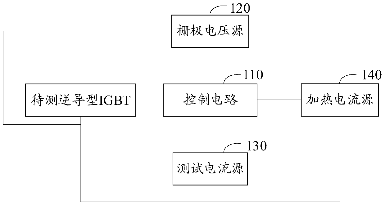
[0020] In one embodiment, such as figure 1 As shown, a thermal resistance test circuit of a reverse conduction type IGBT includes a control circuit 110, a gate voltage source 120, a test current source 130 and a heating current source 140, and the gate voltage source 120, a test current source 130 and a heating current source 140 are all connected to the control circuit 110, the gate voltage source 120, the test current source 130, the heating current source 140 and the control circuit 110 are all used to connect the reverse conduction IGBT to be tested, wherein the reverse conduction IGBT to be tested includes a gate, a collector electrode and emitter, the control circuit 110 controls the test current source 130 to output a reverse test current to the reverse conduction type IGBT to be tested to obtain a preset reverse test current condition, the voltage drop between the collector and the emitter of the reverse conduction type IGBT to be tested With the curve of the junction ...


PUM


Abstract

The invention relates to a thermal resistance test circuit and method for a reverse conducting IGBT. The circuit comprises a control circuit, a gate voltage source, a test current source and a heatingcurrent source. The gate voltage source, the test current source and the heating current source are connected with the control circuit. The gate voltage source, the test current source, the heating current source and the control circuit are connected with the reverse conducting IGBT to be tested. The control circuit controls the test current source, the heating current source and the gate voltagesource to provide reverse test current, forward heating current and gate voltage respectively. When heating is carried out, after the reverse conducting IGBT to be tested is in forward conduction, power heating is carried out. When testing is carried out, the reverse conducting IGBT integrates a reverse diode, and reverse test current is input to record the cooling curve of the reverse conductingIGBT to be tested. A thermal resistance value is acquired according to the cooling curve and a temperature-sensitive coefficient. The problem of inaccurate test caused by a rebound phenomenon duringa forward test is avoided. The thermal resistance test is highly accurate.

Description

technical field [0001] The invention relates to the field of semiconductor testing, in particular to a thermal resistance testing circuit and method of a reverse conduction type IGBT. Background technique [0002] The reverse conduction insulated gate bipolar transistor is a new type of IGBT device. It integrates the IGBT cell structure and the fast recovery diode (FRD) cell structure on the same chip. The reverse conduction IGBT device has a small size, High power density, low cost, high reliability and many other advantages, but the voltage bounce phenomenon of reverse conduction IGBT limits its practical application. [0003] Due to the snapback phenomenon of the existing reverse conduction IGBT thermal resistance test circuit, the thermal resistance measured by the reverse conduction IGBT under low power conditions is inaccurate. Therefore, the accuracy of traditional thermal resistance testing is low. Contents of the invention [0004] Based on this, it is necessary...

Claims


Application Information

Patent Timeline
Patent Type & Authority Patents(China)
IPC IPC(8): G01R31/26
CPCG01R31/2601
Inventor 陈媛张鹏陈义强骆成阳贺致远
Owner CHINA ELECTRONICS PROD RELIABILITY & ENVIRONMENTAL TESTING RES INST
Why Eureka
Try Eureka