Low temperature test box

A low-temperature test and box technology, applied to radio wave measurement systems, instruments, etc., can solve the problems of difficult to ensure the airtightness of the cable interface on the side wall, the low cooling phase rate of the test box, and the difficulty in meeting the production tasks, etc., to achieve a compact structure , Save labor assembly costs, test the effect of strong anti-interference ability

Pending Publication Date: 2018-09-25
WUXI HUACE ELECTRONICS SYST
View PDF0 Cites 2 Cited by
  • Summary
  • Abstract
  • Description
  • Claims
  • Application Information

AI Technical Summary

Problems solved by technology

When there are many test components, it is difficult to ensure the airtightness of the cable interface on the side wall, which leads to a low cooling phase rate of the test chamber and affects production efficiency; when there are few test components, it is difficult to meet the production tasks

Method used


Image

  • Low temperature test box
  • Low temperature test box

Examples


Embodiment Construction

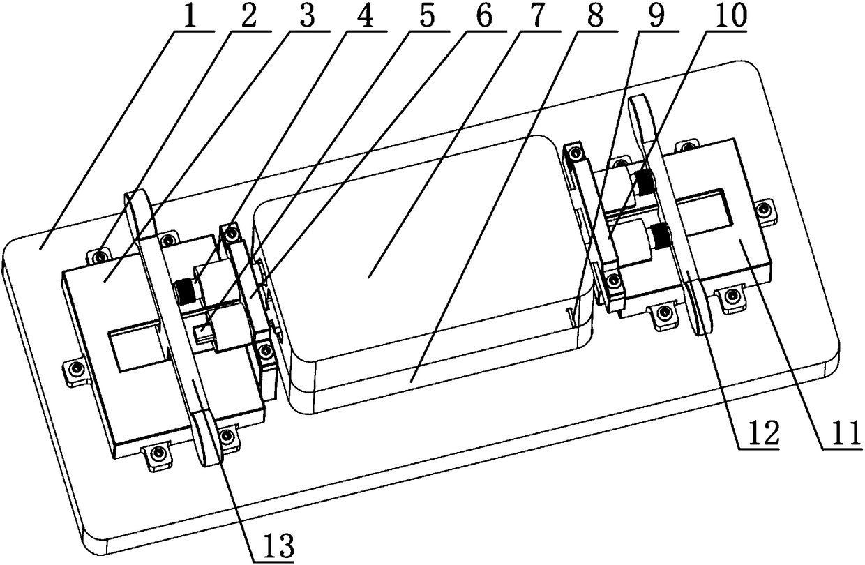
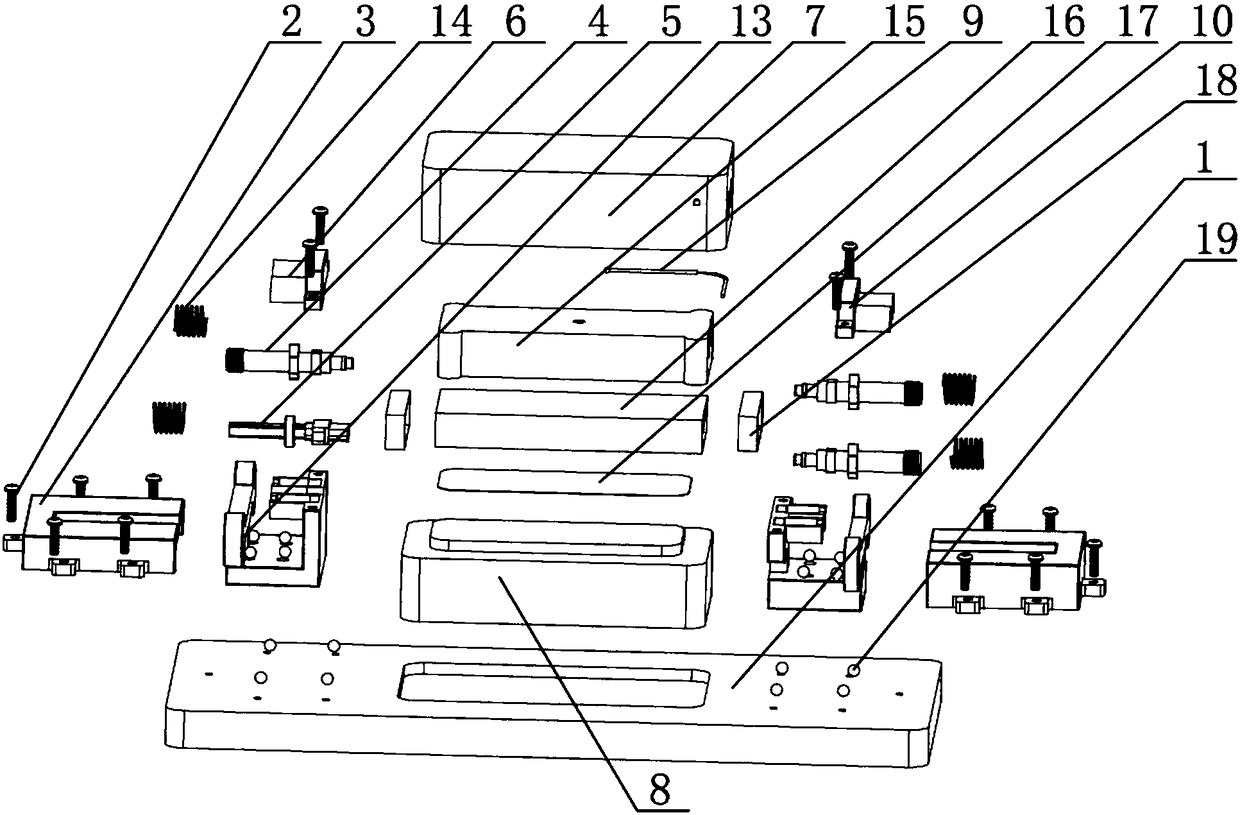
[0021] The specific implementation manner of the present invention will be described below in conjunction with the accompanying drawings.

[0022] like figure 1 and figure 2 As shown, the low temperature test box of this embodiment includes a bottom plate 1, and the two ends of the bottom plate 1 are respectively symmetrically installed with assembly port slide rails 3 and antenna port slide rails 11 through balls 19, and assembly port slide rails 3 are installed with assembly port slide rails. block 13, the antenna port slide 12 is installed on the antenna port slide rail 11, the assembly port slide 13 and the antenna port slide 12 are relatively symmetrically arranged, and have the same structure; the collection port slide 13 and the antenna port slide 12 are all installed There are SMP connectors 4 and rectangular connectors 5 arranged in parallel intervals, the top of the two connectors located at the assembly port slider 13 is installed with the collection port pressure...


PUM


Abstract

A low temperature test box includes a bottom plate; two ends of the bottom plate are symmetrically mounted with a collecting port sliding rail and an antenna port sliding rail respectively through balls; a collecting port slider is mounted on the collecting port sliding rail, and an antenna port slider is mounted on the antenna port sliding rail; a SMP connector and a rectangular connector which are arranged in parallel and spaced from each other are arranged on each of the collecting port slider and the antenna port slider; a collecting port pressing block is arranged on the tops of the two connectors located at the collecting port slider; an antenna port pressing block is arranged on the tops of the two connectors located at the antenna port slider; a hole is formed in the center of thebottom plate; a cold-retaining cover plate is arranged in the hole; a test product is placed on the upper part of the cold-retaining cover plate; product picking-placing belts are arranged on two endsof the test product; the outer part of the test product is covered by a cold-retaining box; a temperature measurement sensor is arranged in the cold-retaining box; two holes are formed in each of twoends of the cold-retaining box; and the SMP connectors and the rectangular connectors stretch into the through holes. The low temperature test box is high in working efficiency, and can meet the usedemands.

Description

technical field [0001] The invention relates to the technical field of test devices, in particular to a low-temperature test box for X-band transceiver components. Background technique [0002] Some performance index tests of X-band transceiver components need to be carried out in a low temperature environment. The test is carried out using an existing cryogenic chamber, and the test cable needs to pass through the side wall of the chamber. When there are many test components, it is difficult to ensure the airtightness of the cable interface on the side wall, which leads to a low cooling phase rate of the test chamber and affects production efficiency; when there are few test components, it is difficult to meet the production tasks. Contents of the invention [0003] The applicant provides a low-temperature test box for the above-mentioned shortcomings in the existing production technology, so that the test work of the X-band transceiver components can be easily completed...

Claims


Application Information

Patent Timeline
Patent Type & Authority Applications(China)
IPC IPC(8): G01S7/40
CPCG01S7/4004
Inventor 俞民良刘均东
Owner WUXI HUACE ELECTRONICS SYST
Why Eureka
Try Eureka