Linkage response method for security monitoring system

A security monitoring and linkage technology, used in closed-circuit television systems, burglar alarms, electrical alarms, etc., can solve the problems of unstable signal, serious impact on analysis and judgment, blurring, etc., to improve the camera effect and avoid storage capacity. limited effect

Inactive Publication Date: 2018-09-25
美澳视界(厦门)智能科技有限公司
View PDF5 Cites 8 Cited by
  • Summary
  • Abstract
  • Description
  • Claims
  • Application Information

AI Technical Summary

Problems solved by technology

At the same time, due to environmental and other reasons, the signal collected by the camera device is unstable or blurred, which will seriously affect the analysis and judgment of the abnormal situation of the accident or abnormal place, so that the most effective abnormal response plan or accident or abnormal cause analysis cannot be implemented.

Method used


Image

  • Linkage response method for security monitoring system
  • Linkage response method for security monitoring system

Examples


Embodiment 1

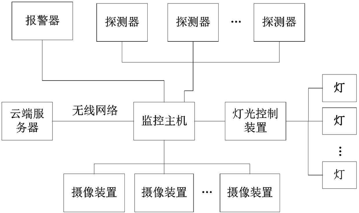
[0030] A linkage response method for a security monitoring system, the security monitoring system involved, as attached figure 1 It includes several detectors, light controllers and several lights connected thereto, at least one camera device, a monitoring host, and an alarm, and the monitoring host is respectively connected to the detectors, light controllers, camera devices, and alarms . The detector is used to monitor abnormal conditions in real time; the user of the camera device collects video signals and / or image signals, and the alarm device is used to generate alarm information; the light controller is used to control the working status of several lights.

[0031] It also includes a cloud server, the cloud server is connected to the monitoring host through a wireless network, and the monitoring host uploads the monitoring video to the cloud server.

[0032] Preferably, the detector in the method of the present invention is an infrared detector, and the infrared detect...

Embodiment 2

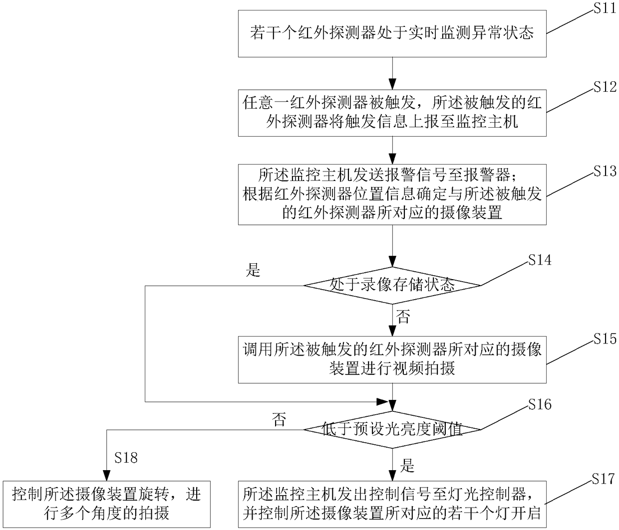
[0048] A linkage response method for a security monitoring system. The security monitoring system includes several detectors, a lighting controller and several lights connected thereto, at least one camera device, a monitoring host, and an alarm. Detectors, light controllers, camera devices, and alarms are connected; the linkage response method of the security monitoring system includes the following steps:

[0049] Step S21, several detectors are in real-time monitoring abnormal state;

[0050] Step S22, any detector is triggered, and the triggered detector reports the trigger information to the monitoring host;

[0051] Step S23, the monitoring host sends an alarm signal to the alarm after receiving the trigger information of the detector, and determines the position information of the detector according to the port information of the triggered detector, and determines the location information of the detector according to the position information of the detector. The camera...


PUM


Abstract

The invention discloses a linkage response method for a security monitoring system. When any detector is triggered, the triggered detector reports triggering information to a monitoring host; after the monitoring host receives the triggering information of the detector, alarming signals are sent to an alarm, the position information of the detector is determined according to the port information of the triggered detector, and according to the position information of the detector, a photographing device corresponding to the triggered detector is determined; the photographing device corresponding to the triggered detector is called for video photographing; and when the luminance value of the current environment is lower than a preset luminance threshold, the monitoring host sends control signals to a light controller, and a plurality of lamps corresponding to the photographing device are controlled to be on. The linkage response method has the advantages that multi-device quick linkage response is achieved, an abnormal position is positioned quickly, video monitoring in a dark condition is met, and multiple grades of abnormal response mechanisms are formed.

Description

technical field [0001] The invention relates to the technical field of security monitoring, in particular to a linkage response method of a security monitoring system. Background technique [0002] In the security monitoring system, when the detector detects an abnormality, it sends out an alarm signal, and the police officer receives the alarm signal, and can see all the images within the scope of authority in the duty room. Perform playback to realize motion anomaly detection and alarm, manually view and then determine the specific location of the alarm signal, and then execute the corresponding response, which is limited by the judgment speed of the police, and the response speed to the alarm signal is limited. At the same time, due to environmental and other reasons, the signal collected by the camera device is unstable or blurred, which will seriously affect the analysis and judgment of the abnormal situation of the accident or abnormal place, so that the most effective...

Claims


Application Information

Patent Timeline
Patent Type & Authority Applications(China)
IPC IPC(8): G08B13/24G08B13/19H04N7/18
CPCG08B13/2494G08B13/19H04N7/18
Inventor 陈美林
Owner 美澳视界(厦门)智能科技有限公司
Why Eureka
Try Eureka