High-efficiency automatic nicking device

A high-efficiency scoring technology, applied in the field of steel scoring, can solve the problems of low scoring accuracy, low applicability, and large dust

Inactive Publication Date: 2018-09-28
刘滨 +2
View PDF6 Cites 2 Cited by
  • Summary
  • Abstract
  • Description
  • Claims
  • Application Information

AI Technical Summary

Problems solved by technology

[0003] The purpose of the present invention is to solve the problems in the prior art that the scoring of steel is generally carried out by manual hand-held machinery, the scoring precision is low, the dust is large, the work efficiency is low, and the applicability is low, and a high-efficiency Efficient automated scoring device

Method used


Image

  • High-efficiency automatic nicking device
  • High-efficiency automatic nicking device
  • High-efficiency automatic nicking device

Examples


Embodiment Construction

[0020] The following will clearly and completely describe the technical solutions in the embodiments of the present invention with reference to the accompanying drawings in the embodiments of the present invention. Obviously, the described embodiments are only some, not all, embodiments of the present invention.

[0021] In describing the present invention, it should be understood that the terms "upper", "lower", "front", "rear", "left", "right", "top", "bottom", "inner", " The orientation or positional relationship indicated by "outside", etc. is based on the orientation or positional relationship shown in the drawings, and is only for the convenience of describing the present invention and simplifying the description, rather than indicating or implying that the referred device or element must have a specific orientation, so as to Specific orientation configurations and operations, therefore, are not to be construed as limitations on the invention.

[0022] refer to Figure ...


PUM


Abstract

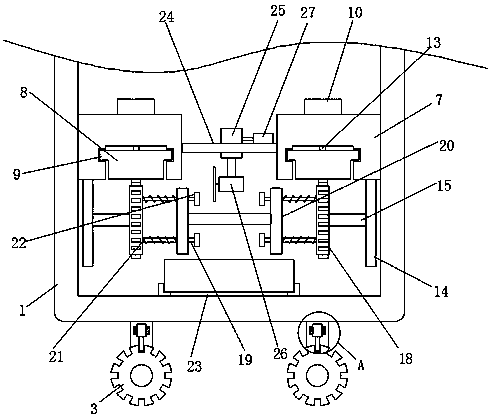
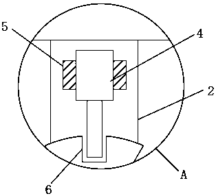
The invention discloses a high-efficiency automatic nicking device. The high-efficiency automatic nicking device comprises a working box; a plurality of supporting legs are disposed on the lower sidewall of the working box; a rotary shaft is inserted into the lower end of each supporting leg; each rotary shaft is sleeved with a rolling wheel; the inner walls of the two sides of the working box are each fixedly connected with a fixing plate; the lower side wall of each fixing plate is provided with a sliding groove; each sliding groove is internally and slideably connected with a sliding plate; the upper side wall of each fixing plate is provided with a slide groove; a sliding rail is disposed between the inner walls of the two sides of each slide groove; each sliding rail is sleeved witha linear motor; and the lower side wall of each linear motor is provided with a connecting rod. A to-be-nicked workpiece is clamped and then nicked, the workpiece is nicked in different horizontal positions and in different surfaces, and the nicking device is wider in applicability, simple in structure, convenient and practical.

Description

technical field [0001] The invention relates to the technical field of steel scoring, in particular to a high-efficiency automatic scoring device. Background technique [0002] In industrial manufacturing, after the steel plate is formed, it needs to be scored on a steel plate according to the production requirements. The general steel plate scoring technology is generally pushed to the cutting machine for scoring. This scoring method is done manually, which consumes manual labor and time-consuming operation It is dangerous and easy to be bruised by the cutting machine. In addition, the production efficiency of this embossing method is low. In the process of manual advancement, its speed and straightness will be affected, so the scoring effect is not very ideal. The avoidance of nicks on the steel can improve the overall heat dissipation of the steel, and at the same time, the bonding between the protrusions and the nicks between adjacent steel can also increase the fit, mak...

Claims


Application Information

Patent Timeline
Patent Type & Authority Applications(China)
IPC IPC(8): B23D19/08B23D33/00B23D33/02B23Q5/34B23Q11/00
CPCB23D19/08B23D33/00B23D33/02B23Q5/34B23Q11/0042
Inventor 刘滨耿俊风谷熹臻
Owner 刘滨
Why Eureka
Try Eureka