Mechanical polishing device facilitating chip collection

A mechanical polishing and debris technology, which is applied in the direction of grinding/polishing equipment, metal processing equipment, grinding/polishing safety devices, etc., can solve the problem that the outer part of the polished object cannot be polished well, the equipment is not completely polished, Inconvenient collection of debris, etc., to achieve the effect of convenient and comprehensive polishing, improving the scope of application, and convenient operation

Inactive Publication Date: 2018-09-28
武汉思异汇创科技有限公司
View PDF5 Cites 8 Cited by
  • Summary
  • Abstract
  • Description
  • Claims
  • Application Information

AI Technical Summary

Problems solved by technology

[0004] However, the current polishing equipment is generally simple in structure, so that the polishing of the equipment is very unchanged, and when the equipment is installed with the clamping equipment, often due to the limit principle of the clamping equipment, the outer part of the polished object is often unable to be polished very well. This leads to inco

Method used


Image

  • Mechanical polishing device facilitating chip collection
  • Mechanical polishing device facilitating chip collection
  • Mechanical polishing device facilitating chip collection

Examples


Example Embodiment

[0018] It should be noted that the embodiments of the present invention and the features in the embodiments can be combined with each other if there is no conflict.

[0019] In the description of the present invention, it should be understood that the terms "center", "longitudinal", "transverse", "upper", "lower", "front", "rear", "left", "right", " The orientation or positional relationship indicated by "vertical", "horizontal", "top", "bottom", "inner", "outer" etc. is based on the orientation or positional relationship shown in the drawings, and is only for the convenience of describing the present invention and The description is simplified, rather than indicating or implying that the pointed device or element must have a specific orientation, be constructed and operated in a specific orientation, and therefore cannot be understood as a limitation of the present invention. In addition, the terms "first", "second", etc. are only used for descriptive purposes, and cannot be und...


PUM


Abstract

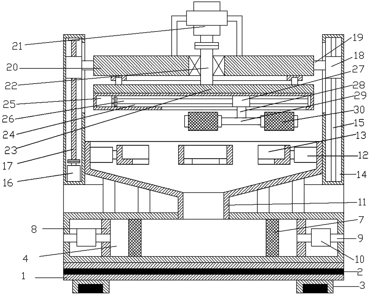
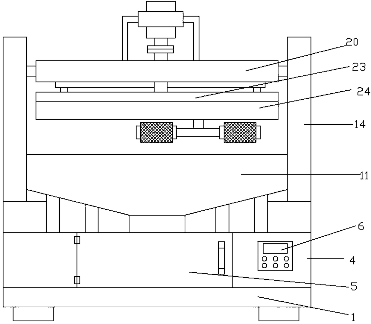
The invention discloses mechanical polishing device facilitating chip collection. The mechanical polishing device comprises a bottom plate, wherein a connecting seat is arranged on the upper side of the bottom plate, and a connecting cover is arranged on the upper side of the connecting seat; telescopic rods are arranged inside the connecting cover, and clamping plates are arranged on the inner sides of the telescopic rods; sliding grooves are formed in the left side and the right side of the connecting cover, a first motor is arranged at the lower end inside one of the sliding grooves, a first screw rod is arranged on the upper side of the first motor, sliding blocks are arranged on the first screw rod and a polishing rod, and connecting rods are arranged on the inner sides of the slidingblocks; supporting plates are arranged inside the connecting rods, a second motor is arranged on the upper side of the supporting plate, a connecting shaft is arranged on the lower side of the secondmotor, a rotating plate is arranged on the lower side of the connecting shaft, and a connecting groove is formed in the lower side of the rotating plate; and a second sliding block is arranged insidethe connecting groove, a connecting rod is arranged on the lower side of the second sliding block, a connecting cross rod is arranged on the lower side of the connecting rod, and polishing rollers are arranged at the left end and the right end of the connecting cross rod. According to the polishing device, chips generated in the polishing process can be effectively collected by device conveniently so that the cleanness of the device can be effectively ensured, and the surrounding environment can be protected.

Description

technical field [0001] The invention relates to the field of machinery, in particular to a mechanical polishing device which is convenient for debris collection. Background technique [0002] Machinery (English name: machinery) refers to the general term of machines and institutions. Machinery is a tool device that can help people reduce the difficulty of work or save labor. Items such as chopsticks, brooms, and tweezers can all be called machines, and they are simple machines. A complex machine is composed of two or more simple machines. These more complex machines are usually called machines. From the point of view of structure and motion, there is no difference between a mechanism and a machine, and it is generally called a machine. [0003] As a commonly used mechanical device, a polishing machine, also known as a grinder, is often used for mechanical grinding, polishing and waxing. Its working principle is: the motor drives the sponge or wool polishing disc installe...

Claims


Application Information

Patent Timeline
IPC IPC(8): B24B41/00B24B55/06B24B41/06B24B55/02B24B41/02B24B47/12
CPCB24B41/007B24B41/02B24B41/06B24B47/12B24B55/02B24B55/06
Inventor 刘文
Owner 武汉思异汇创科技有限公司
Why Eureka
Try Eureka