Robot trailer

A technology of robots and trailers, which is applied to vehicle components, traction connectors, transportation and packaging, etc., and can solve problems such as vehicle damage, vehicles that cannot be fixed, and low flexibility

Inactive Publication Date: 2018-09-28
WUHU BAOYI AMUSEMENT EQUIP
View PDF0 Cites 0 Cited by
  • Summary
  • Abstract
  • Description
  • Claims
  • Application Information

AI Technical Summary

Problems solved by technology

[0003] The purpose of the present invention is to provide a robot trailer. When the DC geared motor is working, the kinetic energy generated by the DC geared motor is transmitted to the short joint bearing adjustment rod and the long joint bearing adjustment rod through the bearing and the connecting rocker in turn, and then The short joint bearing adjustment rod and the long joint bearing adjustment rod directly or indirectly drive the walking rod to tilt at a certain angle, so as to solve the problem that the current mobile robot proposed in the above background technology has low flexibility and cannot fix the vehicle for a long time , during the process of trailering the mobile robot, due to the bumps of the road, the vehicle will fall from the robot trailer, causing damage to the vehicle

Method used


Image

  • Robot trailer
  • Robot trailer
  • Robot trailer

Examples


Embodiment 1

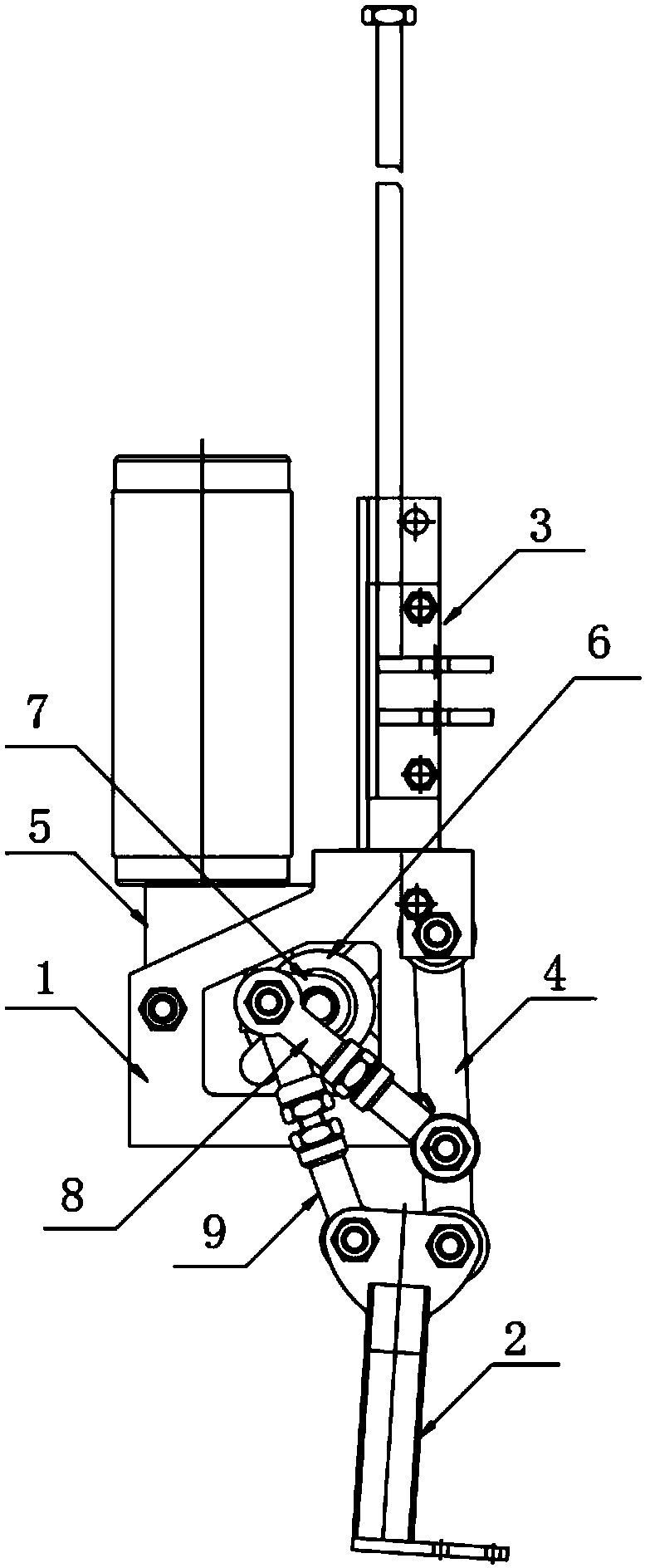
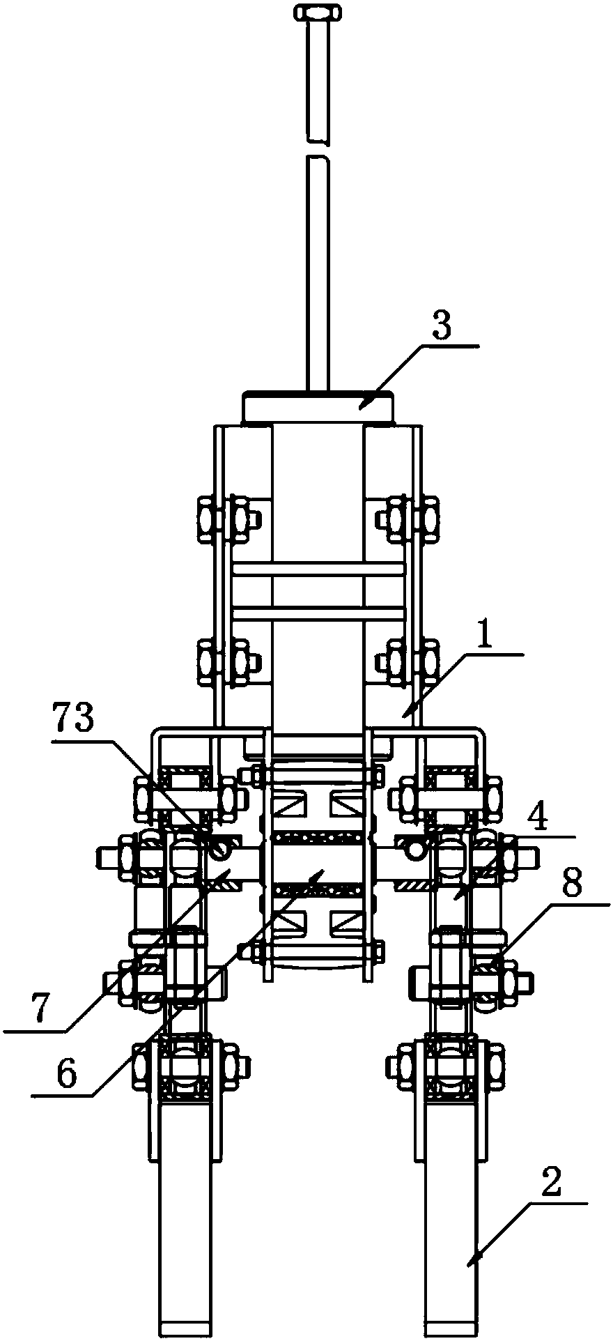
[0027] according to Figure 1-9 The shown robot trailer includes a fuselage body 1, a walking rod 2 and a traction frame 3, the travel rod 2 is arranged on both sides of the bottom end of the fuselage body 1, and the traction frame 3 is arranged on the top end of the fuselage body 1 One side of the top end of the walking rod 2 is movably connected with a connecting rod main body 4, and the other end of the connecting rod main body 4 is movably connected with one side of the fuselage main body 1, and a DC gear motor 5 is fixedly arranged in the fuselage main body 1, The output end of the DC geared motor 5 is provided with a bearing 6, one end of the bearing 6 runs through the fuselage body 1, and extends to one side of the outer wall of the fuselage body 1, and the two ends of the bearing 6 are provided with a connecting rod rocker arm 7, The connecting rod rocker arm 7 is arranged on one side of the outer wall of the fuselage main body 1, and one end of the connecting rod rock...

Embodiment 2

[0030] The difference with embodiment 1 is:

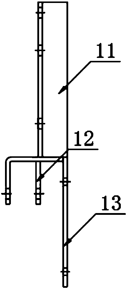
[0031] The fuselage main body 1 includes a fuselage connection plate 11 and a joint bearing connection plate 12, the fuselage connection plate 11 is fixedly arranged on one side of the outer wall of the joint bearing connection plate 12, and one end of the fuselage connection plate 11 is provided with a motor connection plate 13, the motor connecting plate 13 is fixedly arranged on one side of the joint bearing connecting plate 12;

[0032] The walking rod 2 includes a connecting rod side plate 21 and a walking connecting rod 22, the walking connecting rod 22 is fixedly arranged at the bottom end of the connecting rod side plate 21, and the bottom end of the walking connecting rod 22 is fixedly provided with a walking connecting rod bottom plate 23 , one end of the connecting rod main body 4 and the long joint bearing adjusting rod 9 is rotationally connected with the connecting rod side plate 21;

[0033] The traction frame 3 inc...


PUM


Abstract

The invention discloses a robot trailer. The robot trailer comprises a machine body, walking rods and a traction frame. The walking rods are arranged on two sides of the bottom end of the machine body, and the traction frame is arranged at the top end of the machine body. Connecting rod main bodies are movably connected to one sides of the top ends of the walking rods, and the other ends of the connecting rod main bodies are movably connected to one side of the machine body. A direct current gear motor is fixedly disposed in the machine body, and a bearing is disposed at the output end of thedirect current gear motor. One end of the bearing penetrates through the machine body and extends to one side of the outer wall of the machine body, and connecting rod rocker arms are arranged at bothends of the bearing. Through the arrangement of the bearing and the connecting rod rocker arms, the kinetic energy generated by the direct current gear motor is facilitated to transmit to short jointbearing adjusting rods and long joint bearing adjusting rods, so that the short joint bearing adjusting rods and the long joint bearing adjusting rods perform the rotary motion at one ends of joint connecting shafts, and the walking rods walk under direct or indirect action.

Description

technical field [0001] The invention relates to the field of trailer equipment, in particular to a robot trailer. Background technique [0002] Transporting items within a structure or between multiple structures has been somewhat of a problem. Today, many transportation options exist as commercially available products, such as conveyor belts, pneumatic tubes, trailers with universal joints, and mobile robots. A mobile robot or automated guided vehicle is a vehicle that has been equipped with a drive system under computer control. However, the current mobile robot has low flexibility and cannot fix the vehicle for a long time. During the process of trailering the mobile robot, the vehicle will fall from the robot trailer due to the bumps of the road, thus causing damage to the vehicle. Therefore, it is necessary to invent a robot trailer to solve the above problems. Contents of the invention [0003] The purpose of the present invention is to provide a robot trailer. Wh...

Claims


Application Information

Patent Timeline
Patent Type & Authority Applications(China)
IPC IPC(8): B60D1/00B60D1/58B60D1/01B60D1/145
CPCB60D1/00B60D1/01B60D1/145B60D1/58
Inventor 张庆
Owner WUHU BAOYI AMUSEMENT EQUIP
Why Eureka
Try Eureka