
Textile fabric transporting device

A technology for transporting devices and textile fabrics, applied in the field of textiles, can solve problems such as falling, waste of manpower, adverse effects, etc., and achieve the effects of preventing rolling, ensuring safety, and avoiding waste.

Inactive Publication Date: 2018-09-28
XIANGSHUI ZHONGXING TEXTILE CO LTD
View PDF0 Cites 0 Cited by
  • Summary
  • Abstract
  • Description
  • Claims
  • Application Information

AI Technical Summary

Problems solved by technology

[0002] As we all know, fabric transportation is an important process in the textile printing and dyeing workshop. After the textile is completed, the fabric is rolled into rolls and subpackaged. The formation of each roll of fabric is usually driven by the take-up roller and the drive device to wind the fabric on the take-up roller. After a certain amount of fabric has been wound up, it is necessary to remove the coiled roll and replace it with a new roll. However, the traditional method of transporting fabric rolls is to manually carry them, or to The cloth roll fabric is placed on a flatbed truck and pulled by a flatbed truck. However, such a flatbed truck does not have a mechanism for fixing the cloth roll, which may easily cause the cloth roll fabric to roll or even fall off. At the same time, manual pulling wastes manual energy. At the same time, people are usually in front of the car during transportation , it is impossible to observe the condition of the cloth roll fabric at all times, which will cause certain adverse effects in actual use

Method used

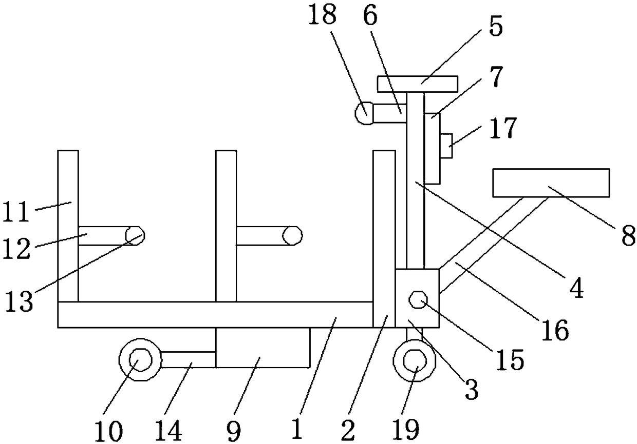
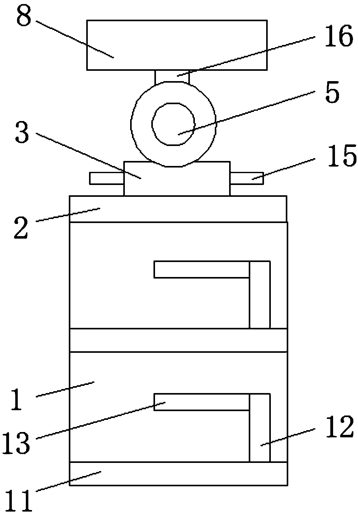

Image

  • Textile fabric transporting device
  • Textile fabric transporting device

Examples


Embodiment Construction

[0018] The following will clearly and completely describe the technical solutions in the embodiments of the present invention with reference to the accompanying drawings in the embodiments of the present invention. Obviously, the described embodiments are only some, not all, embodiments of the present invention.

[0019] In describing the present invention, it should be understood that the terms "upper", "lower", "front", "rear", "left", "right", "top", "bottom", "inner", " The orientation or positional relationship indicated by "outside", etc. is based on the orientation or positional relationship shown in the drawings, and is only for the convenience of describing the present invention and simplifying the description, rather than indicating or implying that the referred device or element must have a specific orientation, so as to Specific orientation configurations and operations, therefore, are not to be construed as limitations on the invention.

[0020] refer to Figure ...


PUM


Abstract

The invention discloses a textile fabric transporting device comprising a supporting plate. A baffle is fixedly connected to the outer wall of one side of the supporting plate. A connecting block is fixedly connected to the outer wall of the side, away from the supporting plate, of the baffle. A steering rod is rotationally connected to the inner surface of the connecting block and perpendicularlypenetrates through the interior of the connecting block. A steering wheel is fixedly connected to the upper end of the steering rod. An illuminating lamp is fixedly connected to the outer wall of theside, close to the baffle, of the steering rod. A control panel is fixedly connected to the outer wall of the side, away from the illuminating lamp, of the steering rod. A seat plate is fixedly connected to the outer wall of the side, away from the baffle, of the connecting block. The textile fabric transporting device is simple in structure, it can be ensured that people observe the situation ofcloth roll fabric in the transporting device at every moment, the purpose that the device is electrically driven can be achieved, waste of labor force due to manual pushing and pulling is avoided, the cloth roll fabric can be effectively fixed, rolling of the cloth roll fabric is prevented, and the safety in the transporting process of the cloth roll fabric is ensured.

Description

technical field [0001] The invention relates to the technical field of textiles, in particular to a textile fabric transportation device. Background technique [0002] As we all know, fabric transportation is an important process in the textile printing and dyeing workshop. After the textile is finished, the fabric is rolled into rolls and divided into packages. The formation of each roll of fabric is usually taken up by the take-up roller driven by the drive device. After a certain amount of fabric has been wound up, it is necessary to remove the coiled roll and replace it with a new roll. However, the traditional method of transporting fabric rolls is to manually carry them, or to The cloth roll fabric is placed on a flatbed truck and pulled by the flatbed truck. However, such a flatbed truck does not have a mechanism for fixing the cloth roll, which may easily cause the cloth roll fabric to roll or even fall off. At the same time, manual pulling wastes manual energy. At t...

Claims


Application Information

Patent Timeline
Patent Type & Authority Applications(China)
IPC IPC(8): B62D63/02B62D63/04
CPCB62D63/02B62D63/04
Inventor 袁以权
Owner XIANGSHUI ZHONGXING TEXTILE CO LTD
Learn More