
Winding and packing device for pipes

A technology for pipes and wrapping tapes is applied in the field of wrapping and packaging devices for pipes, which can solve the problems of damage to the anti-corrosion protective layer, insufficient work efficiency, damage, etc., and achieve the effects of reducing production costs, high processing efficiency, and improving production efficiency.

Pending Publication Date: 2018-09-28
郑州华美彩印纸品有限公司
View PDF0 Cites 3 Cited by
  • Summary
  • Abstract
  • Description
  • Claims
  • Application Information

AI Technical Summary

Problems solved by technology

[0002] Pipes are necessary materials for construction projects. Different pipes require different pipes. The quality of the pipes directly determines the quality of the pipes. Usually, after the pipes are produced by the manufacturer, they need to be wound and packaged to prevent damage during transportation. The surface of the pipe will destroy the anti-corrosion protection layer, thus affecting the performance and service life of the pipe
[0003] At present, the existing winding balers for pipes can only pack the pipes one by one. For large quantities of pipes, the work efficiency is seriously insufficient. It is necessary to equip multiple winding balers to pack the pipes. The equipment purchase cost of large production enterprises, and some production enterprises even cancel the winding and packaging process of pipes due to the high cost of pipe winding and packing machines

Method used


Image

  • Winding and packing device for pipes
  • Winding and packing device for pipes
  • Winding and packing device for pipes

Examples


Embodiment 1

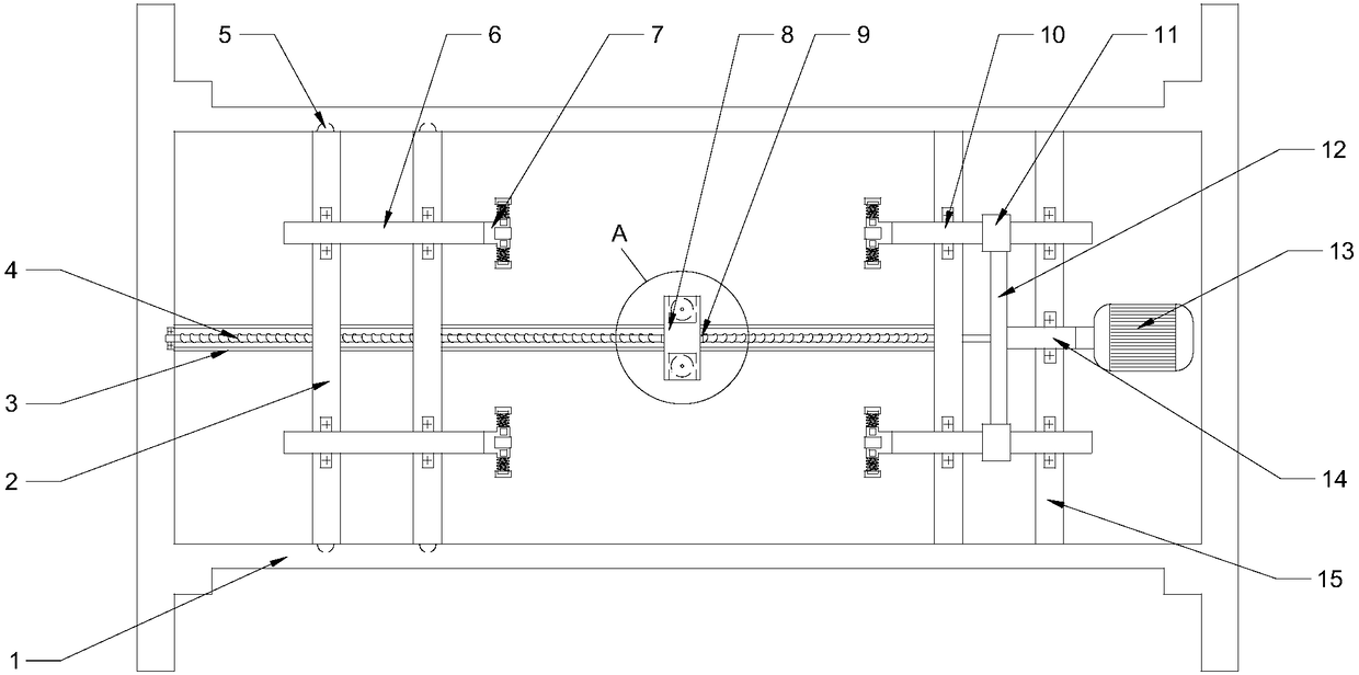
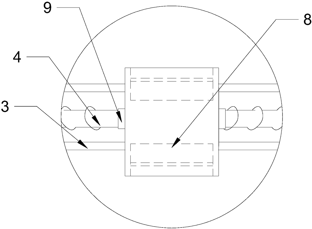
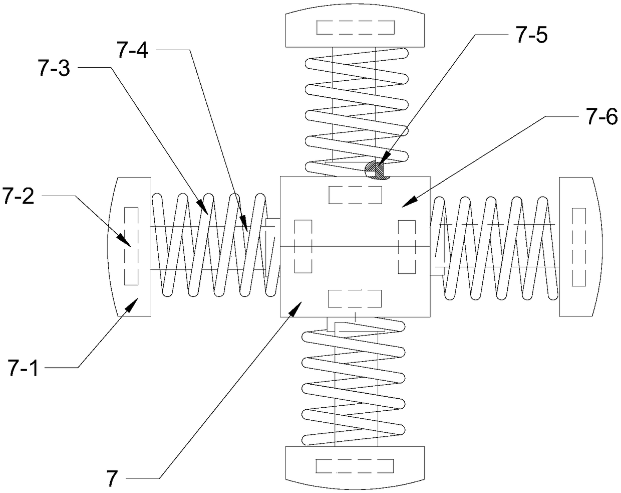
[0027] See Figure 1~4 , A winding and packing device for pipes, including a bracket 1. The bracket 1 is a square frame. The two sides of the square frame are provided with a sliding frame 2 and a fixing frame 15. The sliding frame 2 is provided with a roller 5, and the bracket 1 is There is a roller groove, the roller 5 on the sliding frame 2 is embedded in the roller groove on the bracket 1, and the fixed frame 15 is provided with a driving gear 12 and a plurality of driven gears 11 meshing with the driving gear 12. The driven gear 11 A driven shaft 10 passes through, the driven shaft 10 passes through the fixed frame 15 and is connected to a pipe clamping device 7, a mobile end shaft 6 is installed on the sliding frame 2, and the mobile end shaft 6 passes through the sliding frame 2 to be connected to a pipe clamping device Device 7, the pipe clamping device 7 includes a fixed head 7-6. The fixed head 7-6 is a polygonal cube. The sides of the polygonal cube are provided with...

Embodiment 2

[0030] See Figure 1~4 , A winding and packing device for pipes, including a bracket 1. The bracket 1 is a square frame. The two sides of the square frame are provided with a sliding frame 2 and a fixing frame 15. The sliding frame 2 is provided with a roller 5, and the bracket 1 is There is a roller groove, the roller 5 on the sliding frame 2 is embedded in the roller groove on the bracket 1, and the fixed frame 15 is provided with a driving gear 12 and a plurality of driven gears 11 meshing with the driving gear 12. The driven gear 11 A driven shaft 10 passes through, the driven shaft 10 passes through the fixed frame 15 and is connected to a pipe clamping device 7, a mobile end shaft 6 is installed on the sliding frame 2, and the mobile end shaft 6 passes through the sliding frame 2 to be connected to a pipe clamping device Device 7, the pipe clamping device 7 includes a fixed head 7-6. The fixed head 7-6 is a polygonal cube. The sides of the polygonal cube are provided with...

Embodiment 3

[0034] See Figure 1~4 , A winding and packing device for pipes, including a bracket 1. The bracket 1 is a square frame. The two sides of the square frame are provided with a sliding frame 2 and a fixing frame 15. The sliding frame 2 is provided with a roller 5, and the bracket 1 is There is a roller groove, the roller 5 on the sliding frame 2 is embedded in the roller groove on the bracket 1, and the fixed frame 15 is provided with a driving gear 12 and a plurality of driven gears 11 meshing with the driving gear 12. The driven gear 11 A driven shaft 10 passes through, the driven shaft 10 passes through the fixed frame 15 and is connected to a pipe clamping device 7, a mobile end shaft 6 is installed on the sliding frame 2, and the mobile end shaft 6 passes through the sliding frame 2 to be connected to a pipe clamping device Device 7, the pipe clamping device 7 includes a fixed head 7-6. The fixed head 7-6 is a polygonal cube. The sides of the polygonal cube are provided with...


PUM


Abstract

The invention relates to the field of packing equipment, in particular to a winding and packing device for pipes. The winding and packing device comprises a support, a sliding frame and a fixing frameare correspondingly arranged on the two sides of the inside of the support, a driving gear and a plurality of driven gears meshed with the driving gear are arranged on the fixing frame, driven shaftsare arranged on the driven gears in a penetrating mode, the driven shafts penetrate out of the fixing frame and are connected with pipe clamping devices, the sliding frame is provided with movable end rotating shafts, the movable end rotating shafts penetrate out of the sliding frame and are connected with pipe clamping devices, rolling wheels are arranged on the sliding frame, rolling wheel groove are formed in the support, the rolling wheels on the sliding frame are embedded in the rolling wheel grooves in the support, a ball screw pair parallel to the axes of the driven shafts is connectedbetween the driving gear and the support, the ball screw pair is provided with ball nut, and the ball nut is provided with a winding belt fixing device. According to the winding and packing device for the pipes, the plurality of pipes can be wound and packaged at the same time, and compared with a traditional pipe winding and packing machine, the processing efficiency is high, the production efficiency of an enterprise is improved, and the production cost of the enterprise is reduced.

Description

Technical field [0001] The invention relates to the field of packaging equipment, in particular to a winding and packaging device for pipes. Background technique [0002] Pipes are necessary materials for construction projects. Different pipe fittings need different pipes. The quality of pipes directly determines the quality of pipe fittings. Usually, after the manufacturer produces the pipes, they need to be wrapped and packaged to prevent damage during transportation and transportation. The surface of the pipe destroys the anti-corrosion protective layer, thereby affecting the performance and service life of the pipe. [0003] At present, the existing winding balers for pipes can only pack one pipe one by one. For large quantities of pipes, its work efficiency is seriously insufficient, and multiple winding balers are needed to pack the pipes. The purchase cost of equipment for large-scale production enterprises, and even some production enterprises cancel the winding and packag...

Claims


Application Information

Patent Timeline
Patent Type & Authority Applications(China)
IPC IPC(8): B65B11/04
CPCB65B11/045
Inventor 马艳超
Owner 郑州华美彩印纸品有限公司
Learn More