Automatic braking device for main shaft of machine head of numerically controlled lathe

A CNC lathe and automatic braking technology, which is applied to mechanical equipment, brake types, brake actuators, etc., can solve the problems of poor practicability of the device and performance degradation of the brake device, etc.

Inactive Publication Date: 2018-09-28
ANHUI UNIVERSITY OF TECHNOLOGY AND SCIENCE
View PDF0 Cites 2 Cited by
  • Summary
  • Abstract
  • Description
  • Claims
  • Application Information

AI Technical Summary

Problems solved by technology

[0003] In view of this, the embodiment of the present invention provides an automatic brake device for the main shaft of the CNC lathe head to improve the displacement of the brake stator after the device has been used for a long time, and the distance between the brake armature and the brake stator increases. If the operator does not find out in time Adjustment will easily lead to a decrease in the performance of the brake device and poor practicability of the device

Method used


Image

  • Automatic braking device for main shaft of machine head of numerically controlled lathe
  • Automatic braking device for main shaft of machine head of numerically controlled lathe
  • Automatic braking device for main shaft of machine head of numerically controlled lathe

Examples


Embodiment

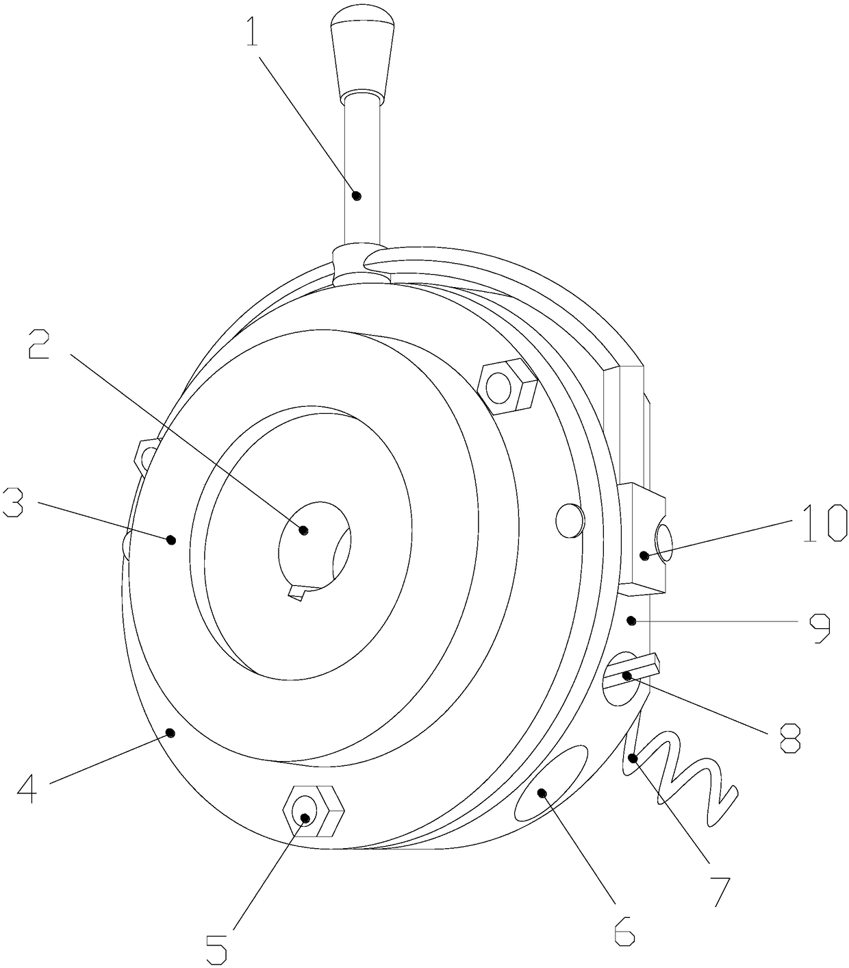
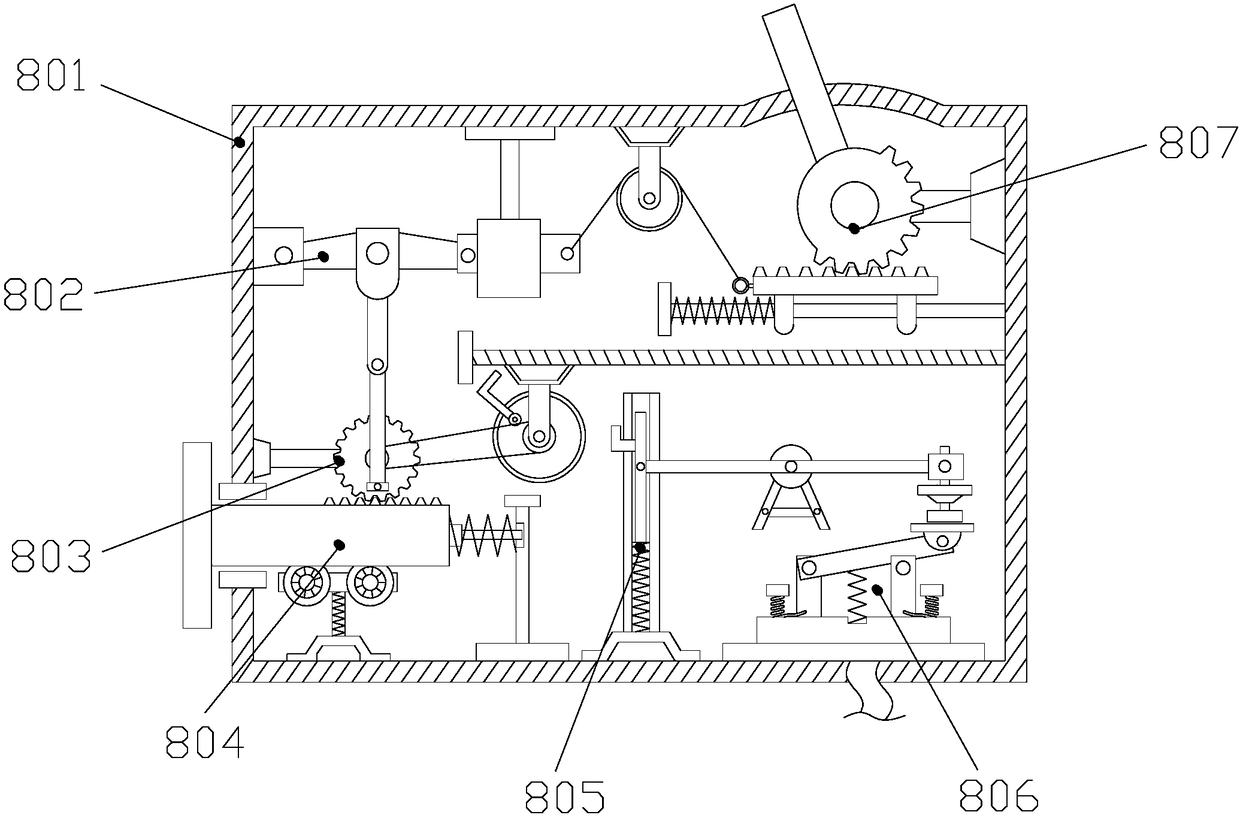
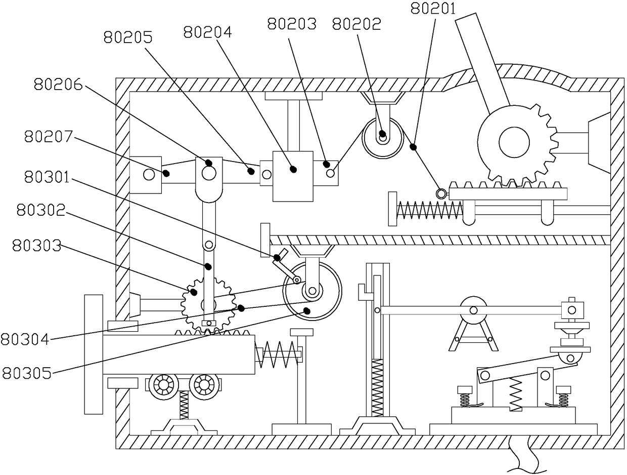
[0021] Such as Figure 1-Figure 5As shown, the present invention provides an automatic braking device for the main shaft of a numerically controlled lathe head. Brake protection device 8, brake stator 9, handle fixing part 10, the brake armature 4 is located in front of the brake stator 9 and the back of the brake armature 4 is close to the front of the brake stator 9, and the main shaft fixing groove 2 is connected through the brake armature 4 and the brake stator 9, the handle fixing part 10 is welded on the left and right sides of the brake stator 9, the release operation handle 1 is located above the brake stator 9 and is mechanically connected with the handle fixing part 10, and the friction plate 3 is installed on the brake The middle of the front of the armature 4 is concentric with the brake armature 4. The back of the product nameplate 6 is glued to the right side of the brake stator 9, and the brake protection device 8 is mechanically connected to the top of the prod...


PUM


Abstract

The invention discloses an automatic braking device for a main shaft of a machine head of a numerically controlled lathe. The device structurally comprises a releasing operating handle, a main shaft fixing groove, a friction sheet, a brake armature, a hollow bolt, a product nameplate, a device power connecting wire, a brake protecting device, a brake stator and a handle fixing part. According to the device, the brake protecting device is mounted and is capable of timely reminding an operator to adjust in case of displacing of a brake stator after long-time use, and thus the performances of theautomatic braking devices are ensured, and the practicability of the device is improved.

Description

technical field [0001] The invention relates to an automatic braking device for a spindle of a CNC lathe head, belonging to the field of automatic braking devices. Background technique [0002] In ordinary CNC lathes, only the turning, threading, drilling and other processing procedures of shaft parts can be carried out, but the milling process cannot be realized. When milling is required, it must be moved to the milling machine. It is troublesome, but it can only be a multi-functional CNC lathe or machining center with more than three axes at the same time. After the ordinary CNC lathe stops, the spindle will continue to rotate due to inertia, and the next step of processing must wait for the spindle to stop. It can be carried out, a lot of time is wasted in the spindle stop process, and work efficiency is reduced. Therefore, an automatic braking device is required to brake the spindle, but the existing technology has a simple structure. The traditional CNC lathe head spind...

Claims


Application Information

Patent Timeline
Patent Type & Authority Applications(China)
IPC IPC(8): F16D66/02F16D65/14F16D121/20
CPCF16D66/02F16D65/14F16D2121/20
Inventor 田丽陈松
Owner ANHUI UNIVERSITY OF TECHNOLOGY AND SCIENCE
Why Eureka
Try Eureka