Pipeline monitoring system

A monitoring system and pipeline technology, applied in pipeline systems, measuring devices, instruments, etc., can solve the problems of difficult data transmission, high operation and maintenance costs, and difficult real-time monitoring, and achieve the effect of reducing costs and ensuring accuracy.

Inactive Publication Date: 2018-09-28
BEIJING INST OF RADIO METROLOGY & MEASUREMENT
View PDF12 Cites 9 Cited by
  • Summary
  • Abstract
  • Description
  • Claims
  • Application Information

AI Technical Summary

Benefits of technology

This patented technology helps detect leaks or cracks on pipelines by combining different types of sensor measurements together with alarm systems that help prevent damage from environmental factors like water intrusion. It also improves upon existing methods such as wireline phone calls and voice transmission over long distances without losing accuracy due to poor signal reception caused by rainwater or snow cover. Overall, this innovative solution provides better quality control measures than previous solutions while maintaining their effectiveness against pipe failures.

Problems solved by technology

The technical problem addressed in this patented text relates to accurately detecting or predicting the extent of damage caused during long term use of underground cables (such as gas lines) that may be vulnerable for environmental factors like water intrusions from rainwater runoff. This requires effective prevention measures against corrosive attack over longer periods without causing significant financial loss or potential harm to human health.

Method used


Image

  • Pipeline monitoring system
  • Pipeline monitoring system
  • Pipeline monitoring system

Examples


Embodiment Construction

[0021] In order to make the purpose, technical solution and advantages of the present invention clearer, the technical solution of the present invention will be clearly and completely described below in conjunction with specific embodiments of the present invention and corresponding drawings. Apparently, the described embodiments are only some of the embodiments of the present invention, but not all of them. Based on the embodiments of the present invention, all other embodiments obtained by persons of ordinary skill in the art without making creative efforts belong to the protection scope of the present invention.

[0022] According to relevant statistics, the annual corrosion loss is far greater than the sum of natural disasters and other accident losses; for example, in 2014, my country's corrosion loss exceeded 2 trillion yuan, four times that of natural disasters. On average, each Chinese person has to bear more than RMB 1,000 in corrosion losses every year. Another exam...


PUM


Abstract

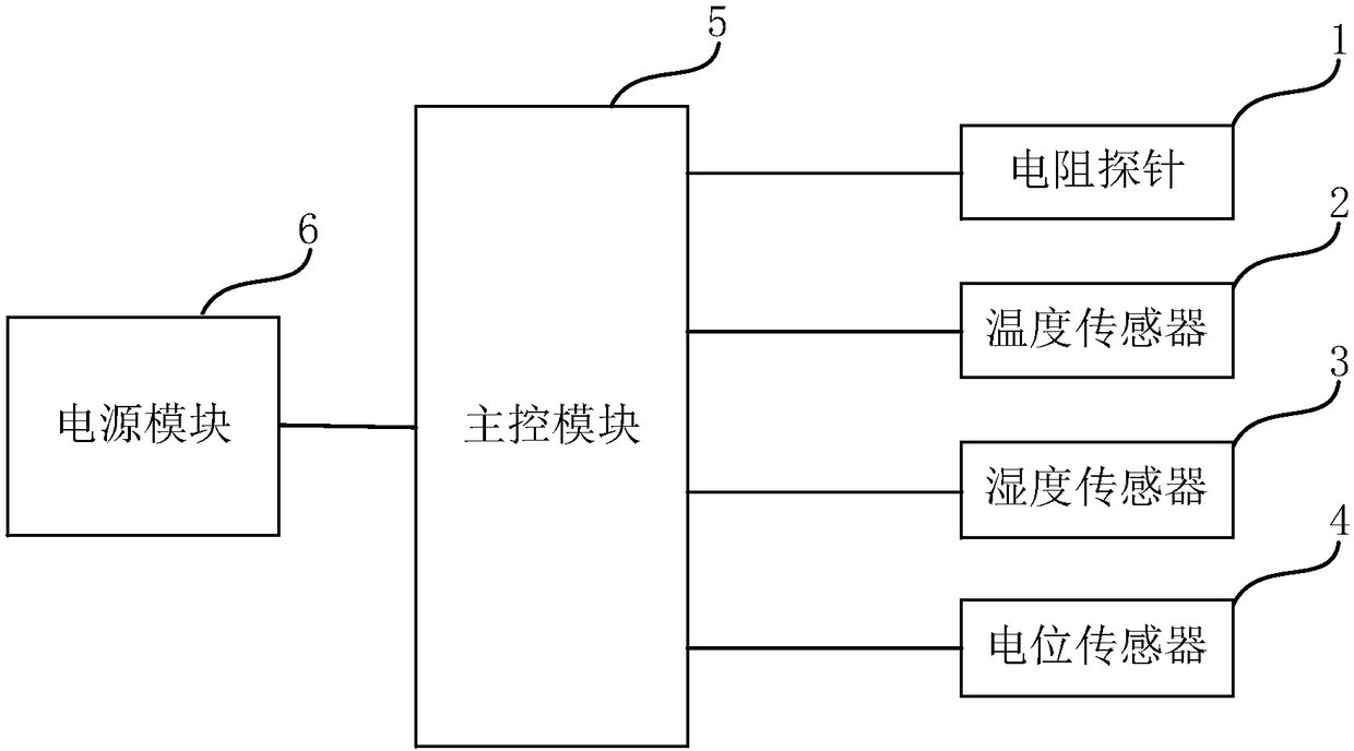
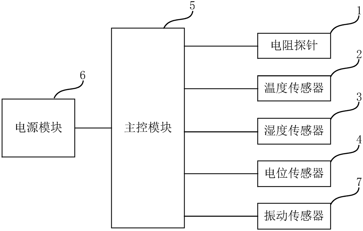
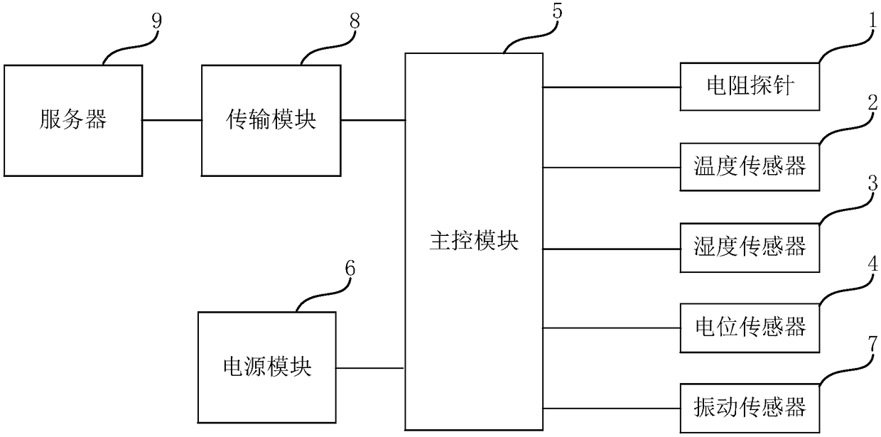
The invention discloses a pipeline monitoring system which solves the problem of difficulties in real-time monitoring of existing systems, inaccurate information acquisition, and high operation and maintenance costs. The system comprises resistance probes, temperature sensors, humidity sensors, potential sensors, a main control module and a power module; the resistance probes are installed on theinner and outer wall surfaces of the pipeline to monitor the long-term corrosion loss of the pipeline; the temperature sensors are evenly distributed along the circumference of the pipeline wall aboutthe axis of the pipe; the humidity sensors are evenly distributed around the pipeline wall along the pipe centerline for detecting pipeline corrosion risks; the potential sensors are evenly distributed around the pipeline wall along the pipeline center line to monitor oxygen absorption corrosion and external stray current corrosion on the outer wall of the pipeline; the main control module is used to obtain the data returned by the resistance probes, the temperature, humidity, and potential sensors and perform monitoring; the power module is used to supply power to the main control module. The pipeline monitoring system realized by the invention effectively solves the problem of real-time monitoring of pipeline corrosion conditions.

Description


Claims


Application Information

Patent Timeline
Owner BEIJING INST OF RADIO METROLOGY & MEASUREMENT
Why Eureka
Try Eureka