FBG-based train dynamic weighing sensor and installation method thereof

A dynamic weighing and sensor technology, which is applied in the field of sensors, can solve the problems such as the large influence of sensor linearity, and achieve the effects of improving weighing accuracy, convenient operation and simple structure

Inactive Publication Date: 2018-09-28
李俊
View PDF0 Cites 4 Cited by
  • Summary
  • Abstract
  • Description
  • Claims
  • Application Information

AI Technical Summary

Problems solved by technology

In the existing clamp-type FBG strain sensor, the external pressure is transmitted to the sensor through the sensor clamp, so the design of the sensor clamp directly affects the measurement result, and has a great influence on the linearity of the sensor

Method used


Image

  • FBG-based train dynamic weighing sensor and installation method thereof
  • FBG-based train dynamic weighing sensor and installation method thereof
  • FBG-based train dynamic weighing sensor and installation method thereof

Examples


Embodiment 1

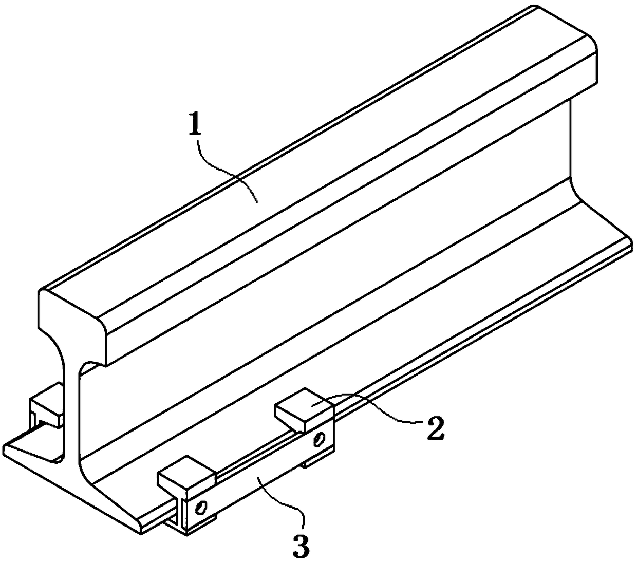
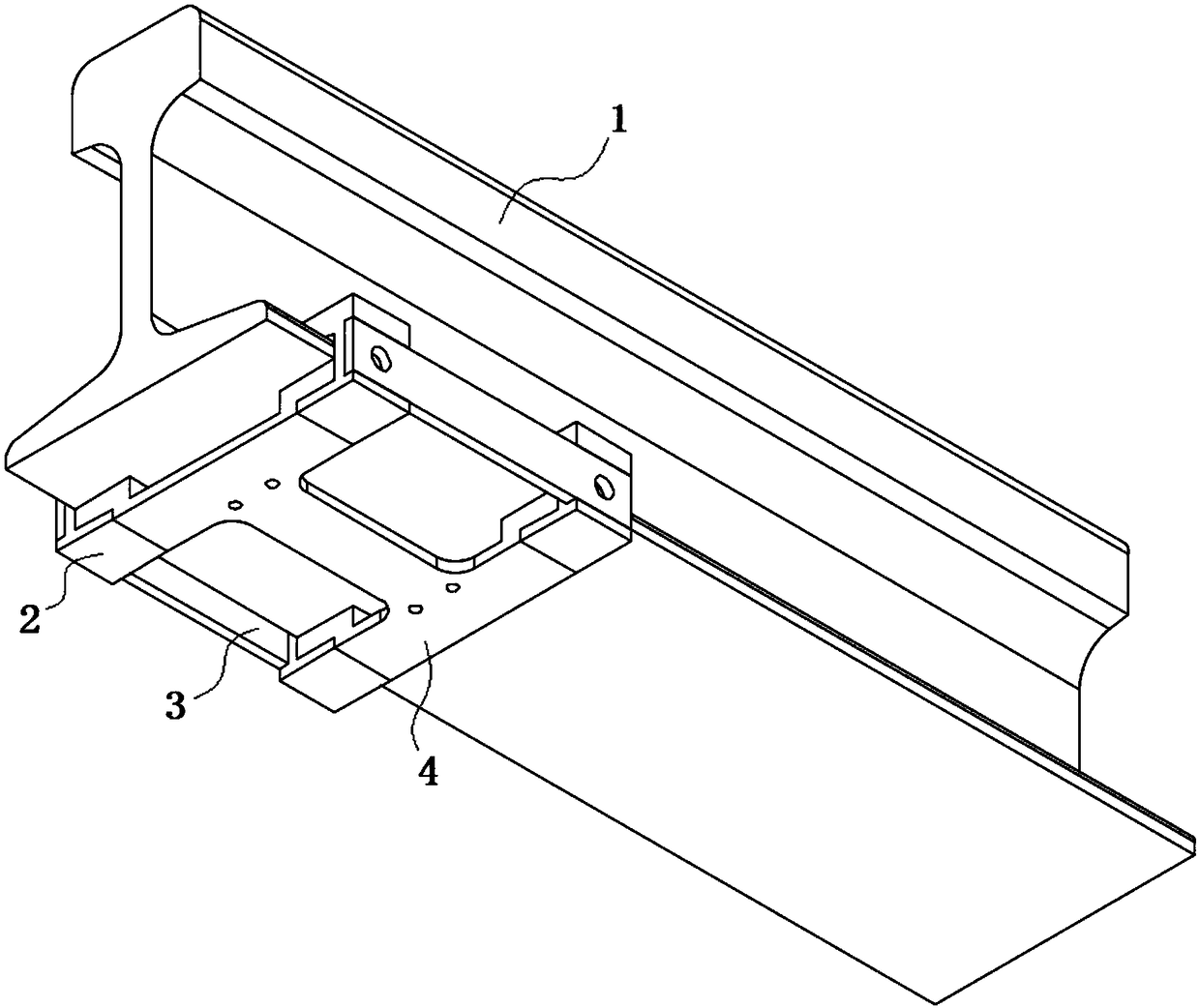
[0049] see Figure 1-6 Shown, the present invention is a kind of train dynamic weighing sensor based on FBG and installation method thereof, comprises two pairs of clamps installed on track 1 and the FBG strain sensor that is fixed between two clamps; Fixture comprises some U-shaped clamp blocks 2 and the bracket; both sides of the bracket are respectively fixed on the base of the track 1 by a pair of U-shaped clamps 2; a connecting plate 3 is fixed between two adjacent U-shaped clamps 2; the two ends of the FBG strain sensor are along the track 1 The straight line direction is fixed on the bracket.

[0050] Wherein, the opposite inner surface of the U-shaped clamp block 2 is a bonding surface 202 matched with the upper surface of the track 1 base; the opposite inner surface of the U-shaped clamp block 2 is matched with the bracket; There is a channel 201 for matching with the connecting plate 3 .

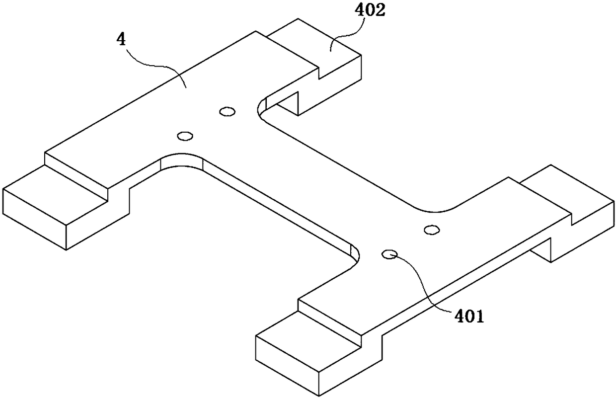
[0051] Wherein, bracket adopts " I " font seat 4, and the end that " I " fon...

Embodiment 2

[0060] see Figure 7-11 Shown, the present invention is a kind of train dynamic weighing sensor based on FBG and installation method thereof, comprises two pairs of clamps installed on track 1 and the FBG strain sensor that is fixed between two clamps; Fixture comprises some U-shaped clamp blocks 2 and the bracket; both sides of the bracket are respectively fixed on the base of the track 1 by a pair of U-shaped clamps 2; a connecting plate 3 is fixed between two adjacent U-shaped clamps 2; the two ends of the FBG strain sensor are along the track 1 The straight line direction is fixed on the bracket.

[0061] Wherein, the opposite inner surface of the U-shaped clamp block 2 is a bonding surface 202 matched with the upper surface of the track 1 base; the opposite inner surface of the U-shaped clamp block 2 is matched with the bracket; There is a channel 201 for matching with the connecting plate 3 .

[0062] Wherein, bracket adopts "=" shape seat 5, and also has threaded hole...


PUM


Abstract

The invention discloses an FBG-based train dynamic weighing sensor and an installation method thereof, and relates to the technical field of sensors. The sensor comprises a plurality of clamps arranged on a rail and an FBG strain sensor fixed between the two clamps; each clamp comprises a plurality of U-shaped clamping blocks and a supporting seat; the two sides of the supporting seat are respectively fixed on the base of the rail through a pair of U-shaped clamping blocks; and a connecting plate is fixed between every two adjacent U-shaped clamping blocks; and the two ends of the FBG strain sensor are fixed on the supporting seat along the linear direction of the rail. By designing a high-stability FBG strain sensor, the FBG strain sensor realizes the real-time measurement of the load onthe rail through integrated stable, firm, fatigue-resistant clamps, and the sensor has the advantages of being high in precision, simple in structure and convenient to operate; the FBG strain sensor is sensitive to axial strain and insensitive to transverse strain due to the characteristics of the FBG strain sensor. The measuring range of the sensor is designed according to the characteristic of the weight of the freight train, and the linear weighing is carried out in the range of 18-100 tons.

Description

technical field [0001] The invention belongs to the technical field of sensors, in particular to an FBG-based train dynamic weighing sensor and an installation method thereof, which are used for real-time overrun detection of overloaded vehicles in the field of railway traffic. Background technique [0002] There are two main methods of vehicle dynamic weighing: vehicle measurement and axle load measurement. As the core device of the dynamic weighing system, the load cell is the input end of the measurement system. At present, copolymer compound piezoelectric sensors, capacitive sensors, bridge weighing platforms, quartz crystal sensitive components, and optical fiber sensors are mainly used in the practical application of dynamic weighing systems at home and abroad. Due to the price, performance, and service life of the above sensors, the accuracy of the dynamic weighing system is likely to be low. The only shortcoming of the quartz crystal sensitive element is that it can...

Claims


Application Information

Patent Timeline
Patent Type & Authority Applications(China)
IPC IPC(8): G01G19/04G01G3/12G01G23/00
CPCG01G19/045G01G3/125G01G23/00
Inventor 李俊杨玉朱思安张睿杰李明雪李明阳郭彦希
Owner 李俊
Why Eureka
Try Eureka