Sample cup transporting device based on analytical sampling equipment

A technology for analyzing sampling and transportation devices, which is applied in the direction of analysis materials, preparation of test samples, instruments, etc. It can solve the problems that the sample cups cannot be shaken and mixed at the same time, and the sample cups cannot be automatically clamped and released, etc., to achieve Facilitate high-speed automatic detection, realize seamless docking, and reduce workload

Inactive Publication Date: 2018-09-28
HUNAN DISAI BIOTECH CO LTD
View PDF0 Cites 0 Cited by
  • Summary
  • Abstract
  • Description
  • Claims
  • Application Information

AI Technical Summary

Problems solved by technology

However, the existing sample cup conveying device has the following problems: (1) the sample cup cannot be automatically clamped and released during the conveying process; (2) the sample cup cannot be shaken and mixed at the same time during the conveying process

Method used


Image

  • Sample cup transporting device based on analytical sampling equipment
  • Sample cup transporting device based on analytical sampling equipment
  • Sample cup transporting device based on analytical sampling equipment

Examples


Embodiment 1

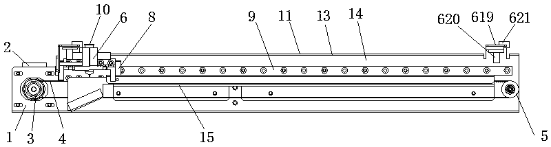
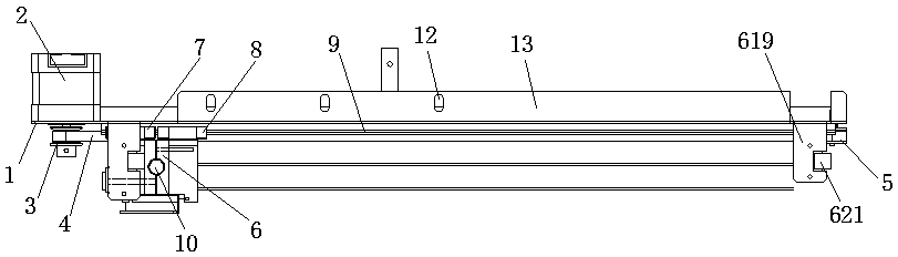
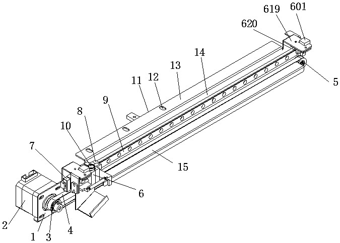
[0029] Such as Figure 1~4As shown, a sample cup transportation device based on analytical sampling equipment includes a frame 1, a driving motor 2, a driving wheel 3, a driven wheel 5 and a transmission belt 4, and the frame 1 is provided with a driving motor 2, Both ends of the frame 1 are respectively provided with a driving wheel 3 and a driven wheel 5, the driving wheel 3 is connected with the output end of the driving motor 2 through a rotating shaft, and the driven wheel 5 is arranged on the side of the frame 1 through a rotating shaft. At the other end, the transmission belt 4 is arranged on the driving wheel 3 and the driven wheel 5 and cooperates with the driving wheel 3 and the driven wheel 5 . The top of the transmission belt 4 is provided with a housing 11, the housing 11 is L-shaped, including a horizontal plate 13 and a vertical plate 14, the lower end of the vertical plate 14 is connected to the frame 1 by welding, and the upper end of the vertical plate 14 is ...

Embodiment 2

[0039] Such as Figure 1~4 As shown, a sample cup transportation device based on analytical sampling equipment includes a frame 1, a driving motor 2, a driving wheel 3, a driven wheel 5 and a transmission belt 4, and the frame 1 is provided with a driving motor 2, Both ends of the frame 1 are respectively provided with a driving wheel 3 and a driven wheel 5, the driving wheel 3 is connected with the output end of the driving motor 2 through a rotating shaft, and the driven wheel 5 is arranged on the side of the frame 1 through a rotating shaft. At the other end, the transmission belt 4 is arranged on the driving wheel 3 and the driven wheel 5 and cooperates with the driving wheel 3 and the driven wheel 5 . The top of the transmission belt 4 is provided with a casing 11, the casing 11 includes a horizontal plate 13 and a vertical plate 14, the lower end of the vertical plate 14 is welded to the frame 1, and the upper end of the vertical plate 14 is connected to the horizontal p...


PUM

PropertyMeasurementUnit
angleaaaaaaaaaa

Abstract

The invention discloses a sample cup transporting device based on analytical sampling equipment. The sample cup transporting device comprises a machine frame, a driving motor, a driving wheel and a driven wheel are arranged on the machine frame, the driving wheel is connected with the output end of the driving motor through a rotary shaft, a driving belt is arranged on the driving wheel and the driven wheel and matched with the driving wheel and the driven wheel, a sliderail is arranged on the machine frame, a first sliding block and a second sliding block are arranged on the sliderail, samplecup clamping units are arranged on the first sliding block and the second sliding block, and the sample cup clamping units are fixedly connected with the driving belt. The sample cup transporting device can not only automatically clamp and transport sample cups, but also can automatically release the sample cups, and can shake the sample cups up in the transporting process.

Description

technical field [0001] The invention relates to the technical field of analysis and sampling equipment, in particular to a sample cup transport device based on analysis and sampling equipment. Background technique [0002] In the medical testing process, testing containers similar to sample cups must be used. After the sample cup is filled with samples and reagents, they need to be evenly mixed, and then transported to the detection instrument for incubation and detection. However, the existing sample cup conveying device has the following problems: (1) the sample cup cannot be automatically clamped and released during the conveying process; (2) the sample cup cannot be shaken and mixed simultaneously during the conveying process. Contents of the invention [0003] The purpose of the present invention is to overcome the deficiencies of the prior art and provide a sample cup transport device based on analytical sampling equipment. [0004] The technical scheme that the pr...

Claims


Application Information

Patent Timeline
Patent Type & Authority Applications(China)
IPC IPC(8): G01N1/38G01N35/04
CPCG01N1/38G01N35/04
Inventor 王加强谢文锋赵营超
Owner HUNAN DISAI BIOTECH CO LTD
Why Eureka
Try Eureka