Equipment and method for testing high-speed tensile stress and strain of material

A technology of stress-strain testing and high-speed stretching, which is applied in the direction of analyzing materials, applying stable tension/pressure to test material strength, measuring devices, etc., which can solve the problem of inability to effectively carry out car crash simulation analysis, and does not consider the signal oscillation of the force sensor , It is difficult to accurately describe the constitutive relationship and other problems, to achieve the effect of improving clarity, simple structure, and strong timeliness

Inactive Publication Date: 2018-09-28
武汉钢铁有限公司
View PDF9 Cites 23 Cited by
  • Summary
  • Abstract
  • Description
  • Claims
  • Application Information

AI Technical Summary

Problems solved by technology

When the strain rate is greater than 100 / s, the stress wave of the sample will reflect back and forth under the high-speed strain rate, the signal measured by the force sensor of the testing machine fluctuates greatly, the stress-strain curve vibrates obviously, and the accuracy of the data is greatly improved. Reduced, it is difficult to accurately describe the constitutive relationship under material dynamics, and it is impossible to effectively carry out automobile crash simulation analysis
The patent application with the publication number CN105651598A and the publication date of 2016.06.08 discloses a high-speed strain testing device and method based on a line-scan camera. , the device and method do not consider the vibration of the force sensor signal at high speed, so the test results are not accurate

Method used


Image

  • Equipment and method for testing high-speed tensile stress and strain of material
  • Equipment and method for testing high-speed tensile stress and strain of material
  • Equipment and method for testing high-speed tensile stress and strain of material

Examples


Embodiment Construction

[0035] In order to make the object, technical solution and advantages of the present invention clearer, the present invention will be further described in detail below in conjunction with the accompanying drawings and embodiments. It should be understood that the specific embodiments described here are only used to explain the present invention, not to limit the present invention.

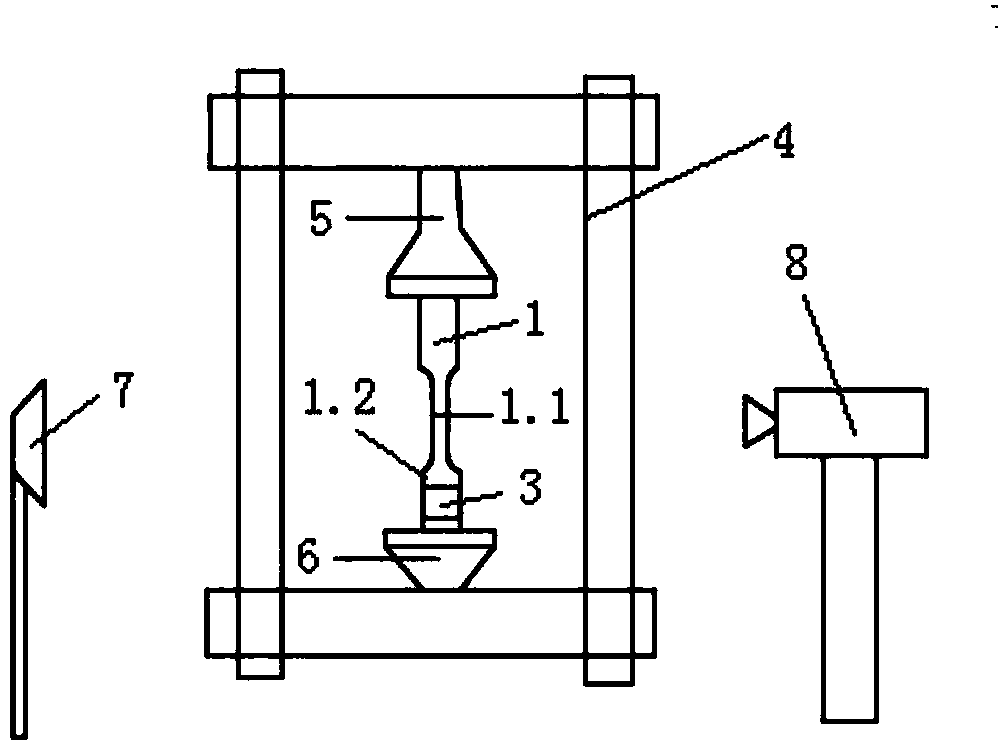
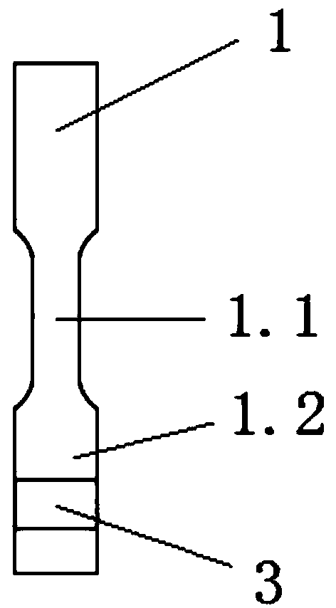
[0036] see figure 1 and figure 2 , a high-speed tensile stress-strain test equipment for materials, which includes a sample 1, a high-speed tensile testing machine 4, a strain gauge 3, a strain gauge, a light source 7, a high-speed camera 8, and a controller. Sample 1 is in the shape of a dumbbell, with a parallel segment 1.1 in the middle and an elastic segment 1.2 in the lower part, and speckles are sprayed on the parallel segment 1.1. The sample 1 is fixed on the high-speed tensile testing machine 4 through the upper clamp 5 and the lower clamp 6 . The high-speed tensile testing machine 4 is...


PUM


Abstract

The invention discloses equipment for testing high-speed tensile stress and strain of a material. The equipment comprises a test sample, a high-speed tensile testing machine, a strain gauge, a light source, a high-speed camera and a controller, wherein the test sample is shaped like a dumbbell, the middle part thereof is a parallel section, the lower part thereof is an elastic section, and the parallel section is sprayed with speckles; the high-speed tensile testing machine is used for stretching the test sample; the strain gauge is stuck on the elastic section of the test sample; a strain meter is used for receiving data transmitted from the strain gauge; the light source is used for aligning a test part of the test sample so as to make the speckles sprayed on the surface of the test sample clearly visible; the high-speed camera is used for aligning the parallel section of the test sample; the controller is used for receiving data transmitted from the high-speed tensile testing machine, the high-speed camera and the strain meter, and drawing a stress-strain curve of the test sample. The invention further provides a method for testing the high-speed tensile stress and strain of thematerial. Through the equipment and the method, the problem of oscillation of the stress-strain curve of the material under a high strain rate can be effectively solved, so that a test result becomesaccurate.

Description

technical field [0001] The invention belongs to the field of mechanical behavior testing of materials, and in particular relates to a high-speed tensile stress-strain testing device and method for materials, mainly aimed at testing thin-gauge steel plates, aluminum alloys, plastics, composite materials, etc. for automobiles. Background technique [0002] The safety of a car can be reflected in the ability to absorb the impact energy and the degree of protection for the occupants during the collision process of the car body. During the collision process, the deformation of the material is a dynamic response with a high strain rate. The dynamic mechanical behavior under the conditions can guide the optimization of structural design, rational selection of materials, and improvement of vehicle body safety in the development process of automobile lightweight. [0003] In the characterization of material mechanical behavior, since the tensile test can obtain indicators such as ten...

Claims


Application Information

Patent Timeline
Patent Type & Authority Applications(China)
IPC IPC(8): G01N3/06G01N3/08
CPCG01N3/068G01N3/08
Inventor 陈明魏星刘渊媛黄全伟董蓓彭周陈寅余立
Owner 武汉钢铁有限公司
Why Eureka
Try Eureka