Parallel multi-channel transmission light assembly having backlight monitoring function

A multi-channel, light-transmitting technology, applied in the field of optical communication, can solve problems such as the inability to realize backlight monitoring and not all channels are used, and achieve the effect of passive coupling packaging solutions

Active Publication Date: 2018-09-28
WUHAN HUAGONG GENUINE OPTICS TECH
View PDF4 Cites 0 Cited by
  • Summary
  • Abstract
  • Description
  • Claims
  • Application Information

AI Technical Summary

Problems solved by technology

[0005] The purpose of the present invention is to provide a parallel multi-channel transmission optical assembly for backlight monitoring, which aims to solve the problem that the existing optical assembly cannot realize the backlight monitoring of more channels and that all channels of the existing array lens are not fully used

Method used


Image

  • Parallel multi-channel transmission light assembly having backlight monitoring function
  • Parallel multi-channel transmission light assembly having backlight monitoring function
  • Parallel multi-channel transmission light assembly having backlight monitoring function

Examples


Embodiment 1

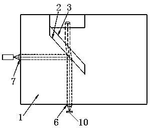
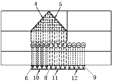
[0025] Such as figure 1 and figure 2 As shown, Embodiment 1 of the present invention provides a parallel multi-channel transmission optical assembly with backlight monitoring, including a lens base 1, an incident collimating lens array 6, a backlight monitoring collimating lens array 8, an outgoing focusing lens array 7, and a receiving end focusing Lens array 9, VCSEL chip array 10, backlight monitoring chip array 11 and receiving chip array 12, described VCSEL chip array 10 and described incident collimating lens array 6 coupling alignment, described backlight monitoring chip array 11 and described backlight The monitoring collimator lens array 8 is coupled and aligned, the receiving chip array 12 is coupled and aligned with the receiving end focusing lens array 9 , and each chip of each chip array is in one-to-one correspondence with each lens of the corresponding lens array. In this embodiment, the incident collimating lens array 6 and the backlight monitoring collimatin...

Embodiment 2

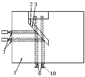
[0031] Such as image 3 and Figure 4As shown, Embodiment 2 of the present invention provides a parallel multi-channel transmission optical assembly with backlight monitoring, including a lens base 1, an incident collimating lens array 6, a backlight monitoring collimating lens array 8, an outgoing focusing lens array 7, and a receiving end focusing Lens array 9, VCSEL chip array 10, backlight monitoring chip array 11 and receiving chip array 12, described VCSEL chip array 10 and described incident collimating lens array 6 coupling alignment, described backlight monitoring chip array 11 and described backlight The monitoring collimator lens array 8 is coupled and aligned, the receiving chip array 12 is coupled and aligned with the receiving end focusing lens array 9 , and each chip of each chip array is in one-to-one correspondence with each lens of the corresponding lens array. The incident collimating lens array 6 and the backlight monitoring collimating lens array 8 adopt ...


PUM


Abstract

The invention provides a parallel multi-channel transmission light assembly having a backlight monitoring function. The assembly comprises a lens base body, an incident collimating lens array, a backlight monitoring collimating lens array, an emergent focusing lens array, a VCSEL chip array and a backlight monitoring chip array; the incident collimating lens array and the backlight monitoring collimating lens array are arranged on the same side of the lens base body, and the emergent focusing lens array is arranged on the other side of the lens base body; a first 45-degree interface and a second 45-degree interface which are parallel to each other are arranged on the lens base body, and a third 45-degree interface and a fourth 45-degree interface which are perpendicular to each other are further arranged on the lens base body. According to the invention, the backlight monitoring of parallel multi-channel transmission can be realized, and an additional lens does not need to be additionally added while the backlight monitoring function is achieved, and the parallel light path channels of the array lens are fully utilized, so that an active coupling and packaging scheme is facilitated, and a passive coupling and packaging scheme is also realized.

Description

technical field [0001] The invention relates to the field of optical communication, in particular to a parallel multi-channel transmission optical component with backlight monitoring. Background technique [0002] With the rapid growth of services such as the Internet, cloud computing, and big data, the large-scale construction of large-capacity and high-bandwidth data centers is being promoted. In the field of optical communication, VCSEL lasers are used as light sources to achieve high-bandwidth transmission, and parallel multi-channels are used to achieve large capacity. [0003] In practical applications, the VCSEL laser is in a non-airtight environment, and the performance of the laser is easily affected by the environment. In particular, the threshold current and output optical power change with temperature and age with long-time operation. In order to ensure that the laser maintains a stable output optical power during use, the output optical power should be monitor...

Claims


Application Information

Patent Timeline
Patent Type & Authority Applications(China)
IPC IPC(8): G02B6/42H04B10/11H04B10/25
CPCG02B6/4286G02B6/4296H04B10/11H04B10/25
Inventor 周纪承张利
Owner WUHAN HUAGONG GENUINE OPTICS TECH
Why Eureka
Try Eureka