Optical device allowing multi-channel light beam splitting to be achieved

A technology of optical beam splitting and optical devices, which is applied in the field of optical communication devices and can solve problems such as backlight current monitoring

Active Publication Date: 2014-08-13
SUZHOU LAXENSE TECH CO LTD
View PDF10 Cites 4 Cited by
  • Summary
  • Abstract
  • Description
  • Claims
  • Application Information

AI Technical Summary

Problems solved by technology

[0003] The purpose of the present invention is to overcome the deficiencies in the prior art, to provide an optical device for realizing multi-channel optical beam splitting, aiming to

Method used


Image

  • Optical device allowing multi-channel light beam splitting to be achieved
  • Optical device allowing multi-channel light beam splitting to be achieved
  • Optical device allowing multi-channel light beam splitting to be achieved

Examples


Embodiment Construction

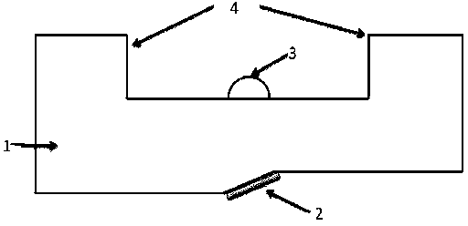
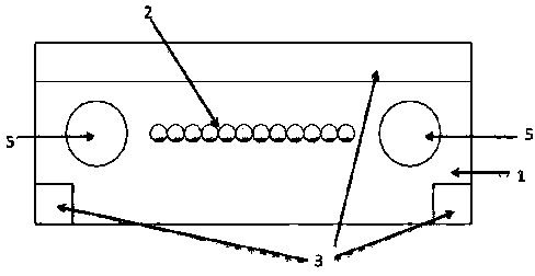
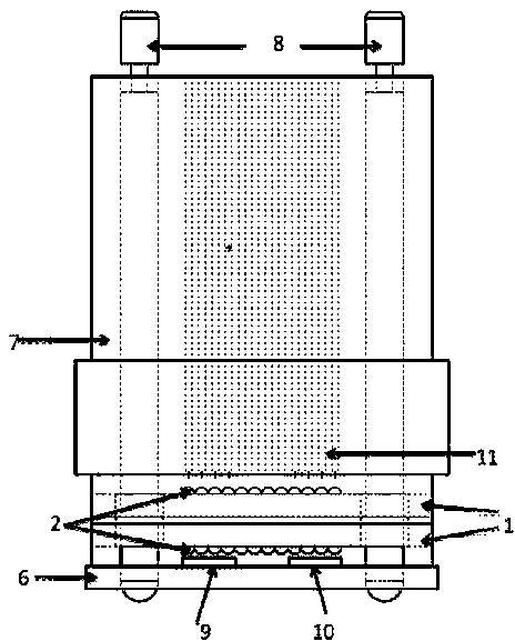
[0017] Such as figure 1 , figure 2 As shown, the optical device for realizing multi-channel light beam splitting includes a base body 1 and a filter 2. The base body 1 is an integral structure formed by one-time resin molding. The upper surface of the base body 1 is provided with a lens array 3 and a raised step 4. The lens The array 3 is located in the central area of ​​the upper surface of the substrate for coupling and alignment between the photoelectric element array and the multimode optical fiber, and the raised steps 4 are located on both sides of the upper surface for forming a suitable lens focal length; the substrate 1 The central area of ​​the lower surface is provided with a slope structure, the center line of the slope structure is on the same plane as the lens array, and the main axis forms a certain angle. On the contrary, the junction between the filter and the inclined surface is coated with a refractive index matching material layer; guide pin holes 5 match...


PUM


Abstract

The invention relates to an optical device allowing multi-channel light beam splitting to be achieved. The optical device comprises a substrate and filters. A lens array and protruding steps are arranged on the upper surface of the substrate, wherein the lens array is located at the center of the upper surface of the substrate, and the protruding steps are located on the two sides of the upper surface of the substrate. An inclined surface structure is located at the center of the lower surface of the substrate, the centerline of the inclined surface structure and the lens array are located on the same plane, and the filters are arranged on the inclined surface of the inclined surface structure and are opposite to the lens array in position. The two sides of the substrate are provided with guide pin holes matched with multi-mode guide pins. The functions of coupling between a multi-channel VCSEL laser device and a multi-mode optical fiber and monitoring of a backlight current can be achieved simultaneously, the structure is simple, cost is low, manufacturing processes are very convenient to implement, and the functions of multi-channel light beam splitting and coupling are achieved passively.

Description

technical field [0001] The invention relates to an optical device for realizing multi-channel optical beam splitting, and belongs to the technical field of optical communication devices. Background technique [0002] With the rise of data centers, optical transceiver modules such as QSFP+ SR4 have also achieved rapid development. However, many manufacturers find it difficult to monitor the backlight current of VCSEL lasers. At present, the problem of backlight current monitoring of the VCSEL laser in the QSFP+ SR4 module cannot be solved. Contents of the invention [0003] The purpose of the present invention is to overcome the deficiencies in the prior art, to provide an optical device for realizing multi-channel optical beam splitting, aiming to solve the problem of backlight current monitoring of VCSEL laser in QSFP+ SR4 module, and to realize multi-channel optical fiber coupling in a passive manner and backlight monitoring. [0004] The purpose of the present invent...

Claims


Application Information

Patent Timeline
IPC IPC(8): G02B6/43
Inventor 贾凌慧孙笑晨冯宁宁
Owner SUZHOU LAXENSE TECH CO LTD
Why Eureka
Try Eureka