Bar-shaped insulator vibratory cementing machine

A technology of insulators and glue-mounting machines, applied in insulators, electrical components, circuits, etc., can solve the problems of low positioning accuracy and work efficiency, large occupation of production sites, and high operating intensity of workers, so as to reduce the number of inputs and production sites, The effect of improving production efficiency and improving strength and quality

Pending Publication Date: 2018-09-28
SINOMA JIANGXI ELECTRICAL PORCELAIN ELECTRIC CO LTD
View PDF7 Cites 1 Cited by
  • Summary
  • Abstract
  • Description
  • Claims
  • Application Information

AI Technical Summary

Problems solved by technology

[0003] Rod insulators need to be filled with cement and other substances in the production process. At present, the rod insulators are glued at both ends at the same time. After adding cement to the steel flange, they are inserted into both ends of the insulator. After manual compression Standing on the glue-mounting machine for 70 hours, there is a defect that the production process takes a long time; by manually supporting the insulator and manually positioning the position, the positioning accuracy and work efficiency are not high, and the worker's operation intensity is high. At the same time, the efficiency of a single glue-mounting machine Low quality leads to more requirements for the number of equipment, large production site occupation, static curing by cement, and low adhesive strength.

Method used


Image

  • Bar-shaped insulator vibratory cementing machine

Examples


Embodiment Construction

[0015] The following will clearly and completely describe the technical solutions in the embodiments of the present invention with reference to the accompanying drawings in the embodiments of the present invention. Obviously, the described embodiments are only some, not all, embodiments of the present invention. Based on the embodiments of the present invention, all other embodiments obtained by persons of ordinary skill in the art without making creative efforts belong to the protection scope of the present invention.

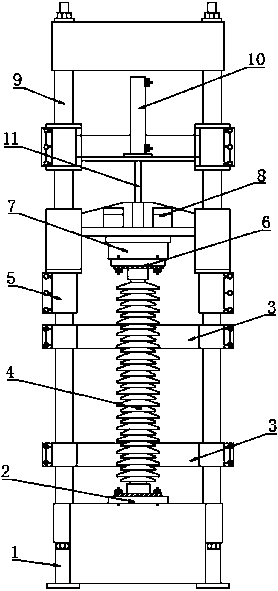
[0016] see figure 1 , in an embodiment of the present invention, a rod-shaped insulator vibrating glue-mounting machine includes a glue-mounting machine body, a lower positioning seat 2, an insulator positioning baffle 3, an adjustable stopper 5, an upper positioning seat 7, an electromagnetic vibrator 8 and a hydraulic pressure Oil cylinder 10; both sides of the lower end of the adhesive machine body are respectively fixedly connected to the frame 1, the lowe...


PUM


Abstract

The invention discloses a bar-shaped insulator vibratory cementing machine. Two sides of the lower end of a cementing machine body are separately fixedly connected with a rack, a lower positioning seat is arranged in the center of the upper end of the rack, an insulator positioning baffle is arranged on the upper portion of the rack, another insulator positioning baffle is arranged on the upper portion of the insulator positioning baffle, a cross plate is arranged on the upper portion of a guide column, the upper portion of the center of the cross plate is fixedly connected with a hydraulic cylinder, and the lower portion of the hydraulic cylinder is slidably connected with the upper portion of the piston rod in a sealed manner; the lower end of the piston rod is fixedly connected with a sliding seat, the upper portions of two sides of the sliding seat are fixedly connected with adjustable limiting stoppers, and two sides of the upper end of the sliding seat are separately fixedly connected with electromagnetic vibrators; and an upper positioning seat is arranged in the center of the lower end of the sliding seat, and the lower end of the upper positioning seat is fixedly connectedwith a steel flange. During cementing of the cementing machine, an upper flange is attracted by an electromagnet, the operation intensity of a worker is reduced, the cementing machine is positioned and placed by the positioning baffles, the positioning precision and the working efficiency are greatly improved, vibration is introduced in a cementing process, and the strength and quality of cementing are greatly improved.

Description

technical field [0001] The invention relates to a glue-fitting device, in particular to a vibrating glue-fitting machine for rod-shaped insulators. Background technique [0002] Rod insulators are widely used in high-voltage transmission lines, and can be used in areas with different harsh environments. They have the characteristics of light weight, small size, unbreakable, high tensile strength, and strong corrosion resistance. [0003] Rod insulators need to be filled with cement and other substances in the production process. At present, the rod insulators are glued at both ends at the same time. After adding cement to the steel flange, they are inserted into both ends of the insulator. After manual compression Standing on the glue-mounting machine for 70 hours, there is a defect that the production process takes a long time; by manually supporting the insulator and manually positioning the position, the positioning accuracy and work efficiency are not high, and the worke...

Claims


Application Information

Patent Timeline
Patent Type & Authority Applications(China)
IPC IPC(8): H01B19/00
CPCH01B19/00
Inventor 阎法强黄灿伟林柏福袁志勇李震尚超峰贾贺军
Owner SINOMA JIANGXI ELECTRICAL PORCELAIN ELECTRIC CO LTD
Why Eureka
Try Eureka