Eureka AIR delivers breakthrough ideas for toughest innovation challenges, trusted by R&D personnel around the world.

A test transformer with built-in reactive power compensation function and power supply system

A technology for testing transformers and functions. It is applied to transformer/inductor components, transformers, variable transformers, etc., and can solve the problems of large size of test transformers, inconvenient operation, and limited application scope.

Active Publication Date: 2019-06-18
山东泰开互感器有限公司
View PDF4 Cites 0 Cited by
  • Summary
  • Abstract
  • Description
  • Claims
  • Application Information

AI Technical Summary

Problems solved by technology

[0004] At present, since most domestic test transformers use oil-immersed insulation, the volume and weight are large, and it is very inconvenient to operate.
On the other hand, the test transformer with oil-immersed insulation is bulky, and it is not easy to integrate with standard voltage transformers and other power equipment, which limits its application range

Method used


Image

  • A test transformer with built-in reactive power compensation function and power supply system
  • A test transformer with built-in reactive power compensation function and power supply system
  • A test transformer with built-in reactive power compensation function and power supply system

Examples


Embodiment Construction

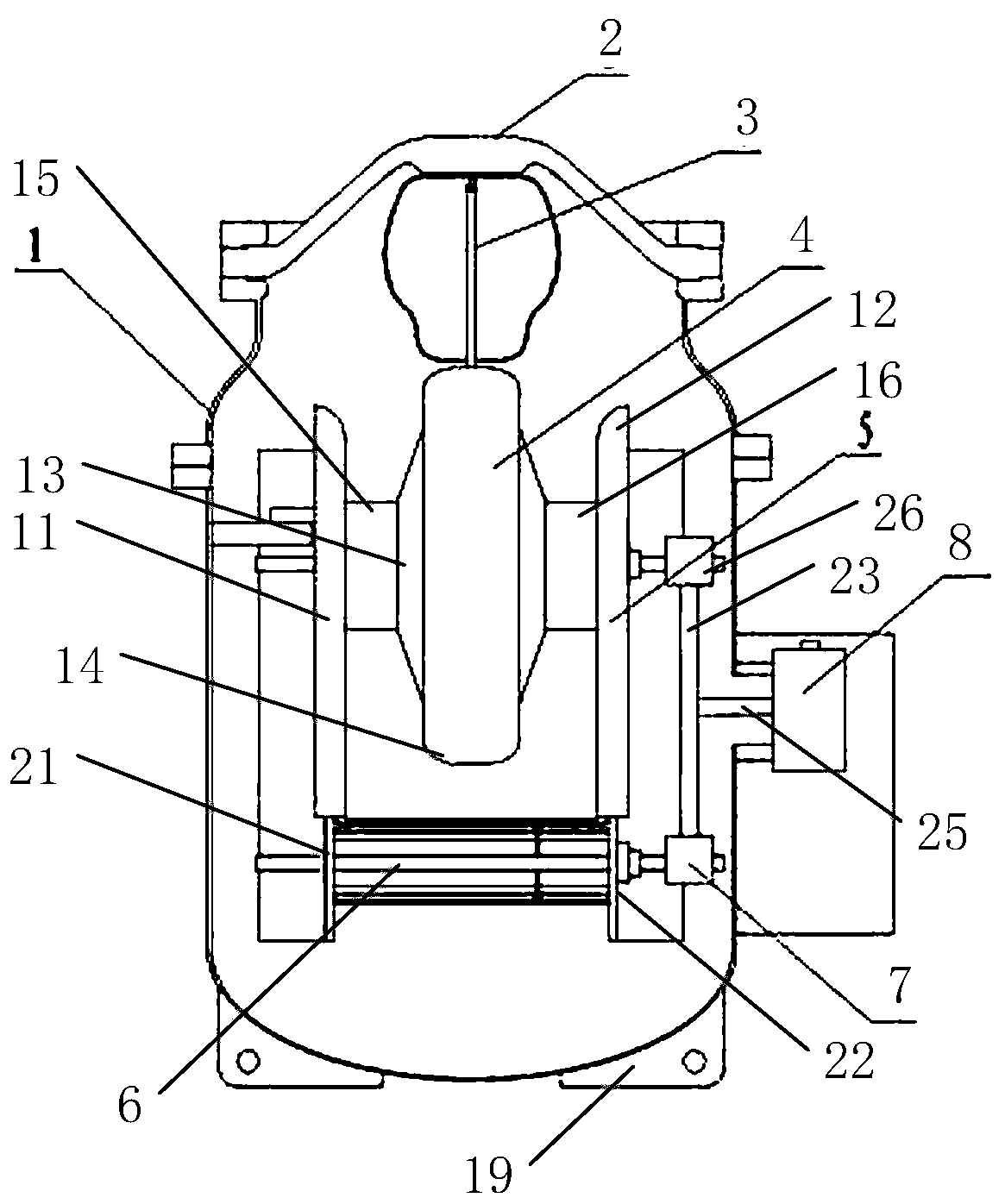
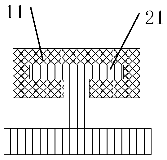
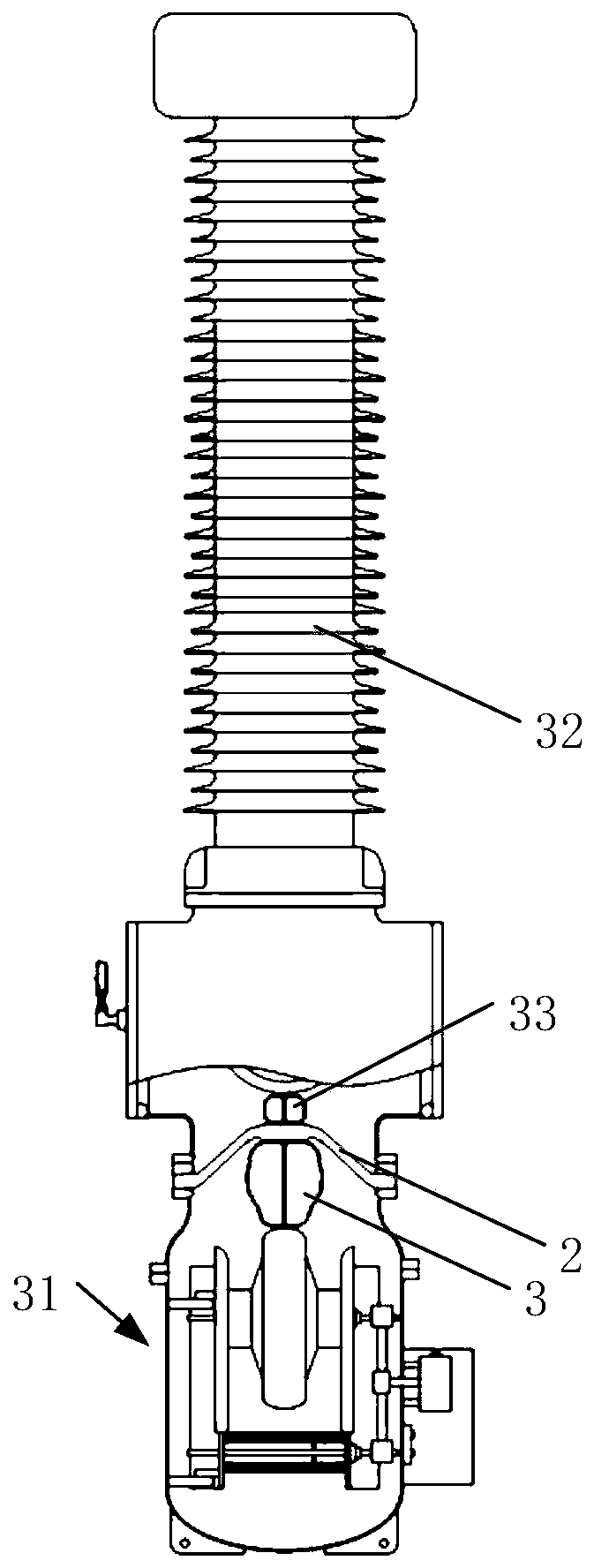
[0039] The invention provides a test transformer with built-in reactive power compensation function, such as figure 1 with figure 2 As shown, it includes: shell 1, insulating part 2, connecting rod 3, mutual induction coil 4, high voltage shielding mechanism 5, excitation module 6, magnetic circuit adjustment mechanism 7 and its power device 8; insulating part 2, connecting rod 3, mutual inductance The coil 4, the high-voltage shielding mechanism 5, the excitation module 6 and the magnetic circuit adjustment mechanism 7 are respectively arranged inside the housing 1; the power device 8 is arranged outside the housing 1;

[0040] Here the housing 1 is an airtight container, and the inside of the housing 1 is filled with SF6 gas. The test transformer is insulated by SF6 gas and sealed with a metal shell, which makes the whole host small in size and light in weight, and SF6 gas has good insulation performance. The excitation module is a silicon steel sheet iron core. The insu...


PUM


Abstract

The invention provides a testing transformer with a built-in reactive compensation function and a power supply system. The testing transformer comprises a shell, an insulating piece, a communication rod, a mutual coil, a high-voltage shielding mechanism, an excitation module, a magnetic path adjusting mechanism and a power device. The excitation inductance of the testing transformer is changed through adjustment of the excitation circuit characteristic of the mutual coil, an air magnetic path of the excitation module is adjusted, and the excitation induction is changed, so that resonance is counteracted in the whole system, and the reactive compensation function is realized. The testing transformer can be turned into an electric reactor for use through adding of the air magnetic path.

Description

technical field [0001] The invention relates to the field of transformers, in particular to a test transformer with a built-in reactive power compensation function and a power supply system. Background technique [0002] With the rapid development of modern industry, industrial power consumption is increasing, and industrial electrical equipment is dominated by motors and high-power rectifiers. Therefore, reactive power and harmonics have become the most prominent problems in the quality of industrial power consumption. The large power transmission line loss will increase and the utilization rate of electric energy will be reduced. [0003] The reactive power compensation methods in the existing power system are mostly based on shunt capacitors and shunt reactors, that is, additional power equipment needs to be specially equipped for reactive power compensation. This not only requires additional power equipment, but also needs to consider secondary wiring. and transportatio...

Claims


Application Information

Patent Timeline
Patent Type & Authority Patents(China)
IPC IPC(8): H01F29/10H01F27/40
CPCH01F27/402H01F29/10
Inventor 李国宾孙绪明颜超潘滨苏本超李振涛李友前耿兵周胜振杨宇鲁法强
Owner 山东泰开互感器有限公司
Why Eureka
Eureka Blog
Learn More