Directional pattern reconfigurable antenna, directional pattern reconfigurable method and wireless terminal device

A technology for reconstructing antennas and directional diagrams, applied in antenna grounding switch structure connections, antennas, antenna arrays, etc., can solve problems such as inability to change antenna radiation range, inflexible dynamic adjustment, complex structure, etc., to improve communication quality and structure Simple, effect of increasing coverage distance

Inactive Publication Date: 2018-09-28
SHANGHAI KANGFEI INFORMATION TECH CO LTD
View PDF4 Cites 5 Cited by
  • Summary
  • Abstract
  • Description
  • Claims
  • Application Information

AI Technical Summary

Problems solved by technology

[0004] The above scheme can control the electromagnetic signal to turn to the selected direction to ensure that the user terminal receives a higher signal strength, but the above scheme uses a motor to control the steering of the antenna to realize the rotation of the antenna and change the antenna pattern. For the current wireless terminal equipment , such as routers, smart home products, etc., which use motors to control antenna steering, there are disadvantages such as too large volume and too complicated structure. Moreover, the antenna system of the above scheme can only realize the rotation of the antenna, that is, it can only change the radiation direction of the antenna from one direction. For another direction, the radiation range of the antenna cannot be changed, nor can the antenna system achieve omnidirectional radiation, and the dynamic adjustment is not flexible enough

Method used


Image

  • Directional pattern reconfigurable antenna, directional pattern reconfigurable method and wireless terminal device
  • Directional pattern reconfigurable antenna, directional pattern reconfigurable method and wireless terminal device
  • Directional pattern reconfigurable antenna, directional pattern reconfigurable method and wireless terminal device

Examples


Embodiment 1

[0035] This embodiment discloses a reconfigurable antenna with a pattern. The pattern is also called a radiation pattern, which refers to a graph in which the relative field strength (normalized modulus) of the radiation field varies with the direction at a certain distance from the antenna. It is usually expressed by two mutually perpendicular plane patterns in the maximum radiation direction of the antenna. The pattern is used to measure the performance of the antenna, and various parameters of the antenna can be observed from the pattern.

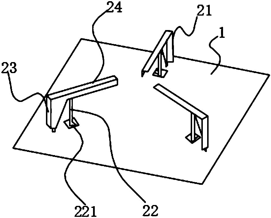
[0036] This pattern reconfigurable antenna includes a PCB board 1 and an array antenna 2 located on the PCB board 1. The array antenna 2 is composed of a plurality of antenna subunits 21, and each antenna subunit 21 is composed of a plug-in antenna. The material of the plug-in antenna is a PCB plug-in or a metal plug-in, and the type of the plug-in antenna here is any one of a monopole antenna, a dipole antenna, or a PIFA antenna. This em...

Embodiment 2

[0050] Such as Figure 10 As shown, this embodiment discloses a method for dynamically adjusting the pattern based on the pattern reconfigurable antenna in Embodiment 1, including the following steps:

[0051] A: The wireless terminal device regularly or irregularly traverses the communication quality with the client in various combination modes and selects the best combination mode corresponding to the best communication quality according to the traversal results;

[0052] Wherein, the concrete method of step A comprises:

[0053] The host of the wireless terminal device regularly or irregularly receives the RSSI value (Received Signal Strength Indicator) fed back by the client in various combination modes, and determines the best combination according to the RSSI value in various combination modes mode, and the host includes a radio frequency processing unit.

[0054] B: Control each antenna sub-unit 21 to be on or off according to the traversal result of step A so that th...

Embodiment 3

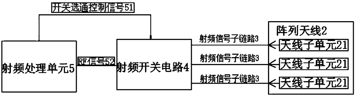
[0063] This embodiment discloses a wireless terminal device using a pattern reconfigurable antenna, such as a wifi device such as a router and a smart home product. The wifi device includes the pattern reconfigurable antenna described in Embodiment 1. Specifically, the The radio frequency signal output by the radio frequency port of the wifi device is connected to the radio frequency switch circuit 4, and the back end of the radio frequency switch circuit 4 is connected to a plurality of radio frequency signal sub-links 3, and each radio frequency signal sub-link 3 is respectively connected to an antenna subunit 21, and through the radio frequency switch The circuit 4 controls the strobing or closing of each radio frequency signal sub-link 3, and can simultaneously strobe one or more sub-links to obtain a combination of multiple groups of different strobing states. The method of use is similar to that of the second embodiment, and is not described here Let me repeat.


PUM


Abstract

The invention discloses a directional pattern reconfigurable antenna, a directional pattern reconfigurable method and a wireless terminal device. The directional pattern reconfigurable antenna includes a PCB and an array antenna arranged on the PCB. The array antenna is formed by multiple antenna subunits, and each subunit is connected to a radio frequency switching circuit via radio frequency signal sub-links. The radio frequency switching circuit is connected to a radio frequency processing unit, and the radio frequency switching circuit is used for controlling gating or closing of each antenna subunit according to switch gating control signals transmitted by the radio frequency processing unit so that the array antenna operates in a specific working mode. The invention has the followingadvantages: dynamical adjusting of a wireless coverage area can be realized, coverage distances can be increased, the received signal strength at user terminals can be enhanced, the communication quality can be improved, etc.

Description

technical field [0001] The invention belongs to the technical field of wireless communication, and in particular relates to an antenna with a reconfigurable pattern, a reconfiguration method and a wireless terminal device. Background technique [0002] At present, most wireless terminal devices, such as routers and smart home products, use omnidirectional antennas to obtain coverage in all directions. But usually there are not users in all directions at a specific moment, and there will be a waste of energy in these directions. If the antenna radiation direction can be directed to users, it can improve the user's received signal strength, improve communication quality, and increase coverage distance. , and the position of the user is often changed dynamically, which requires an antenna type whose pattern can be adjusted dynamically. [0003] In order to solve the above technical problems, people have carried out long-term exploration. For example, a Chinese patent discloses...

Claims


Application Information

Patent Timeline
Patent Type & Authority Applications(China)
IPC IPC(8): H01Q1/36H01Q1/38H01Q1/48H01Q1/50H01Q3/24H01Q21/29H01Q1/24H04B7/08
CPCH01Q1/241H01Q1/36H01Q1/38H01Q1/48H01Q1/50H01Q3/247H01Q21/293H04B7/0857
Inventor 陈西杰
Owner SHANGHAI KANGFEI INFORMATION TECH CO LTD
Why Eureka
Try Eureka