
A Hybrid Reluctance Magnetic Levitation Linear Motor with Bypass Core
A linear motor and magnetic levitation technology, applied in the direction of electromechanical devices, electrical components, electric components, etc., can solve the problems that limit the excellent performance of ordinary linear motors, and achieve the effects of reduced vibration, safe and reliable work, and simple control
- Summary
- Abstract
- Description
- Claims
- Application Information
AI Technical Summary
Problems solved by technology
Method used
Image

Examples
Embodiment Construction
[0024] Attached below Figures 1 to 8 The principle and specific implementation of the present invention will be further described in detail.
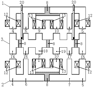
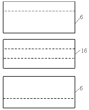
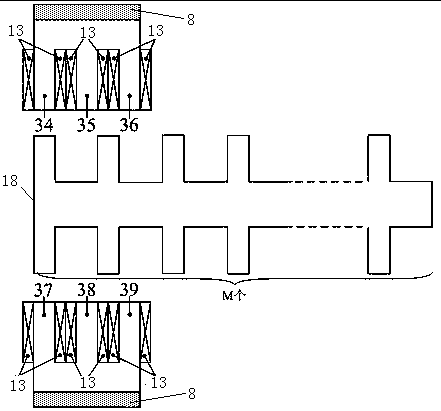
[0025] A hybrid reluctance type magnetic levitation linear motor with a bypass core, including an upper stator 1, a lower stator 2 and a mover 3, the upper stator 1 includes a left suspension core 4, a right suspension core 5, and a left suspension core 4 The left stator bypass core 6 and the right stator bypass core 7 are arranged on the inner side and the inner side of the right suspension core 5 respectively, so that the suspension control magnetic circuit is distributed along the radial plane. Between the left and right stator bypass cores 6 and 7, there is a magnetic isolation aluminum block 8, the left suspension core 4, the right suspension core 5, the left stator bypass core 6, the right stator bypass core 7, and the magnetic isolation aluminum block 8 are connected as a whole, the left control core 9 and the right control cor...
PUM
 Abstract
Description
Claims
Application Information