Latch, two-frequency divider circuit based on current mode logic and frequency divider

A technology of latches and logic units, applied in logic circuits, pulse counters using semiconductor devices, electrical components, etc., can solve the problems that cannot meet the requirements of broadband frequency division and millimeter wave circuit frequency division, and achieve Eliminate the effect of narrow crossover range, improve performance, and increase crossover range

Inactive Publication Date: 2018-09-28
北京何氏咨询策划有限公司
View PDF6 Cites 5 Cited by
  • Summary
  • Abstract
  • Description
  • Claims
  • Application Information

AI Technical Summary

Problems solved by technology

[0004] In the process of realizing the present invention, the inventor finds that the resistance value in the existing latch circuit is fixed, and at least the following defects exist when the current mode logic two frequency divider circuit composed of the existing latch is used for frequency division: although the existing The frequency division range of the current mode logic two frequency divider circuit is relatively wide, but it still cannot meet the requirements of wideband frequency division, and must cover all process corners, so the existing technology has been difficult to meet the frequency division of the current millimeter wave circuit design need

Method used


Image

  • Latch, two-frequency divider circuit based on current mode logic and frequency divider
  • Latch, two-frequency divider circuit based on current mode logic and frequency divider
  • Latch, two-frequency divider circuit based on current mode logic and frequency divider

Examples


Embodiment Construction

[0027] Exemplary embodiments of the present disclosure will be described in more detail below with reference to the accompanying drawings. Although exemplary embodiments of the present disclosure are shown in the drawings, it should be understood that the present disclosure may be embodied in various forms and should not be limited by the embodiments set forth herein. Rather, these embodiments are provided for more thorough understanding of the present disclosure and to fully convey the scope of the present disclosure to those skilled in the art.

[0028] Those skilled in the art can understand that, unless otherwise defined, all terms (including technical terms and scientific terms) used herein have the same meaning as commonly understood by those of ordinary skill in the art to which this invention belongs. It should also be understood that terms, such as those defined in commonly used dictionaries, should be understood to have meanings consistent with the meanings in the co...


PUM


Abstract

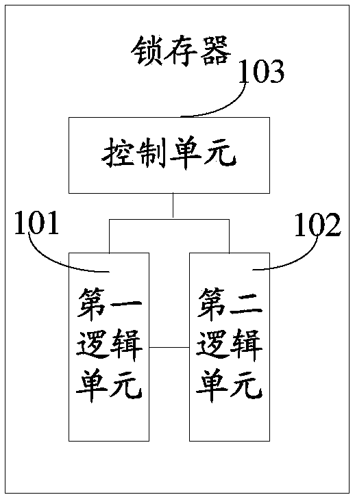
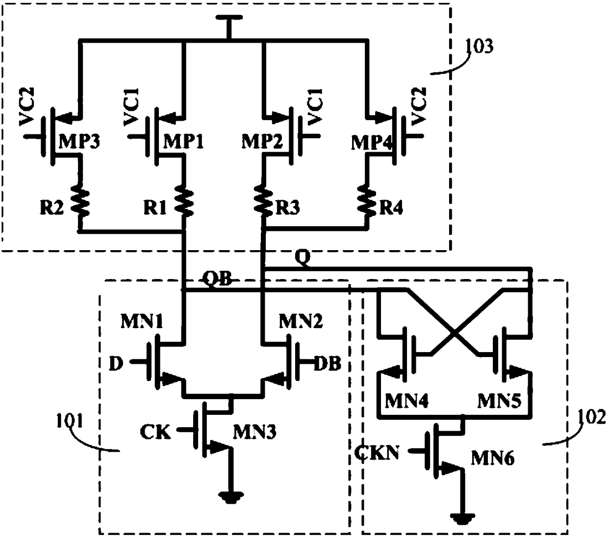
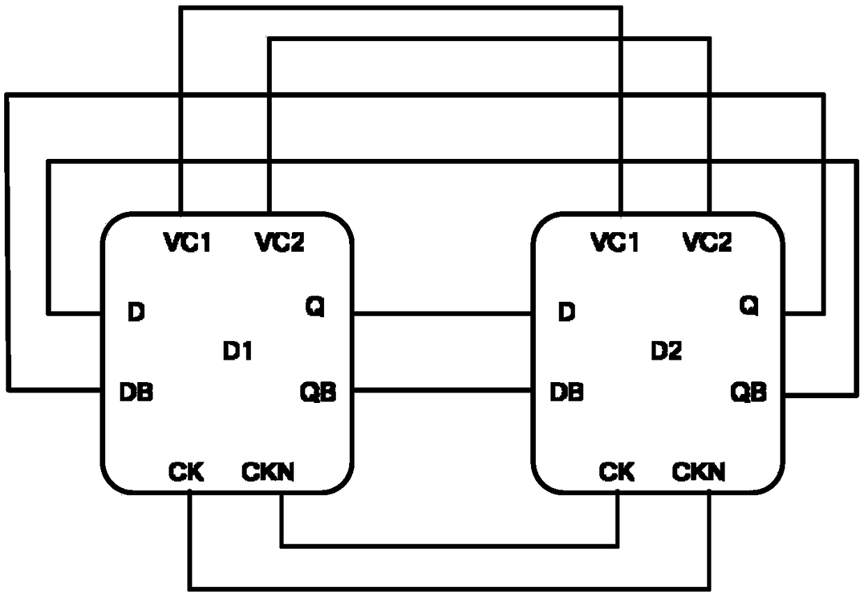
The invention discloses a latch, a two-frequency divider circuit based on current mode logic and a frequency divider. The latch comprises a first logic unit, a second logic unit and a control unit, wherein the first logic unit comprises a first input end, a second input end, a first output end, a second output end and a clock signal positive input end; the second logic unit comprises a third inputend, a fourth input end, a third output end, a fourth output end and a clock signal negative input end; the first output end is coupled with the third input end and the fourth output end; the secondoutput end is coupled with the third output end and the fourth input end; and the control unit is coupled between the first logic unit and a power supply and between the second logic unit and the power supply, and a current path between the power supply and a ground wire is controlled by resistance regulation. The invention provides a latch with a controllable resistance value at the output end; and the frequency divider realized based on the latch can eliminate the problem of narrow frequency division ranges of existing frequency dividers, and can greatly improve the frequency division rangeof the frequency divider.

Description

technical field [0001] The invention relates to the technical field of radio frequency and millimeter wave integrated circuit design, in particular to a latch, a two-frequency divider circuit based on current mode logic, and a frequency divider. Background technique [0002] As the frequency of circuit design continues to increase, millimeter wave circuit design has become a new direction for circuit engineers to compete. The millimeter wave frequency range is 26.5-300GHz, and the bandwidth is as high as 273.5GHz. More than 10 times the full bandwidth from DC to microwave. Even considering atmospheric absorption, only four main windows can be used when propagating in the atmosphere, but the total bandwidth of these four windows can reach 135GHz, which is 5 times the sum of the bandwidths of the microwave bands below. This is undoubtedly very attractive in today's tight frequency resources. Compared with lasers, the propagation of millimeter waves is much less affected by ...

Claims


Application Information

Patent Timeline
Patent Type & Authority Applications(China)
IPC IPC(8): H03K19/094H03K23/00
CPCH03K19/094H03K23/002
Inventor 何建中朱新新
Owner 北京何氏咨询策划有限公司
Why Eureka
Try Eureka