An injection-locked frequency divider circuit with wide locking range

A locking range, injection locking technology, applied in the direction of electrical components, automatic power control, etc., can solve the problems of high operating frequency of regenerative frequency divider, large bandwidth of current-mode logic frequency divider, low power consumption and high operating frequency , to achieve the effect of wide locking range, low power consumption, and improved energy

Active Publication Date: 2021-06-04
FUDAN UNIV
View PDF0 Cites 0 Cited by
  • Summary
  • Abstract
  • Description
  • Claims
  • Application Information

AI Technical Summary

Problems solved by technology

Among them, the current logic frequency divider has a large bandwidth but the operating frequency is not high, the regenerative frequency divider has a high operating frequency but consumes a lot of power, and the injection frequency divider has the characteristics of low power consumption and high operating frequency at the same time, which makes the injection Locked frequency dividers are widely used in ultra-high frequency systems, but the shortcoming of its small frequency division range has always been the main factor limiting its application range. Therefore, the design of injection locked frequency dividers with wide locking range is a current research hotspot and difficulty

Method used


Image

  • An injection-locked frequency divider circuit with wide locking range
  • An injection-locked frequency divider circuit with wide locking range
  • An injection-locked frequency divider circuit with wide locking range

Examples


Embodiment Construction

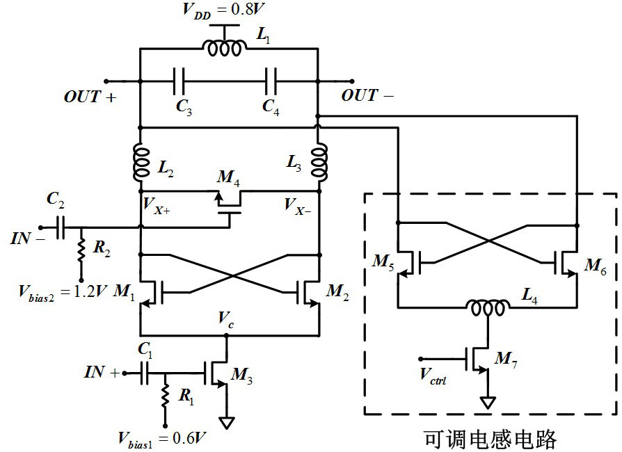
[0029] Such as figure 1 Shown is a wide locking range injection locked divider of the present invention.

[0030] Differential inductance L with center tap 1 and the parasitic capacitance C connected across the inductor 3 、C 4 Constitute the LC resonant cavity, NMOS tube M 1 and M 2 The cross-coupling constitutes a negative resistance to provide the energy required for oscillation; the differential injection signals are respectively transmitted from M 3 Tube and M 4 tube injection, where M 3 The drain of the tube is connected to the cross-coupled tube M 1 and M 2 source (node ​​V c ), M 3 The tube not only provides the tail current but also injects the injection signal IN+ into the node V c ; 4 The tube is a direct injection tube, and its source is connected to M 1 drain of the tube (node ​​V x+ ), whose drain is connected to M 2 drain of the tube (node ​​V x- ), inject the signal IN-through the M 4 The tube is directly injected into the resonant cavity, and t...


PUM


Abstract

The invention belongs to the technical field of radio frequency wireless receiver integrated circuits, in particular to an injection-locked frequency divider circuit with a wide locking range. The injection locked frequency divider includes: on-chip LC resonant cavity, negative resistance circuit, signal injection circuit (including direct injection path and tail current injection path), adjustable inductance circuit for adjusting the self-resonant frequency of the frequency divider, two It is used to isolate the direct injection tube from the inductance-capacitance resonant cavity circuit and the isolation inductance of the adjustable inductance circuit. On the one hand, the present invention effectively utilizes the differential output signal of the front-stage VCO through double injection, and improves the injection energy and injection efficiency; The self-resonant frequency avoids the use of variable capacitors with low Q values ​​at high frequencies, and further broadens the frequency division range of the injection-locked frequency divider. Compared with the prior art, the present invention can remarkably increase the frequency division range of the frequency divider under the condition of ensuring equivalent power consumption.

Description

technical field [0001] The invention belongs to the technical field of radio frequency wireless receiver integrated circuits, and in particular relates to an injection-locked frequency divider applied in a frequency synthesizer of a wireless receiver, which can be used for radio frequency signal receiver chips of technical standards such as wireless broadcasting, communication and global positioning. . Background technique [0002] In recent years, wireless communication systems and other related fields have developed rapidly. Higher transmission rates and larger signal bandwidths are an important direction for its future development. As the main part of the radio frequency transceiver, its performance directly determines the wireless The application prospect of communication system. As an important module of the RF transceiver, the performance of the frequency synthesizer determines whether the entire transceiver can work normally, so the frequency synthesizer used to prov...

Claims


Application Information

Patent Timeline
Patent Type & Authority Patents(China)
IPC IPC(8): H03L7/18
CPCH03L7/18
Inventor 李巍徐媛媛
Owner FUDAN UNIV
Why Eureka
Try Eureka